Earth Observation Mission CFI Software Pointing Software User Manual for JAVA |
Earth Observation Mission CFI Software Pointing Software User Manual for JAVA |
| Code | EO-MA-DMS-GS-025 |
| Issue | 4.31 |
| Date | 18/06/26 |
| Name | Function | Signature | |
| Prepared by: | EOCFI Team | Project Engineers | |
| Checked by: | Inês Estrela | Project Manager | |
| Approved by: | Antonio Gutierrez | Division Head |
| Contract Data | Classification | ||
|---|---|---|---|
| Contract Number: | 4000102614/1O/NL/FF/ef | Internal | |
| Public | |||
| Contract Issuer: | ESA / ESTEC | Industry | X |
| Confidential | |||
| External Distribution | ||
|---|---|---|
| Name | Organization | Copies |
| Electronic handling | ||
|---|---|---|
| Document generator: | Doxygen 1.7.1 | |
| Electronic file name: | eo-ma-dms-gs-015-10 | |
| Issue | Change Description | Date | Approval |
|---|---|---|---|
| 1.0 | These libraries corresponds to version 4.0 of C libraries. | 22/06/09 | |
| 4.1 | These libraries corresponds to version 4.1 of C libraries. | 07/05/10 | |
| 4.2 | These libraries corresponds to version 4.2 of C libraries. | 31/01/11 | |
| 4.3 | These libraries corresponds to version 4.3 of C libraries. | 06/02/12 | |
| 4.4 | These libraries corresponds to version 4.4 of C libraries. | 05/07/12 | |
| 4.5 | These libraries corresponds to version 4.5 of C libraries. | 01/03/13 | |
| 4.6 | These libraries corresponds to version 4.6 of C libraries. | 03/10/13 | |
| 4.7 | These libraries corresponds to version 4.7 of C libraries. | 28/03/14 | |
| 4.8 | These libraries corresponds to version 4.8 of C libraries. | 29/10/14 | |
| 4.9 | These libraries corresponds to version 4.9 of C libraries. | 23/04/15 | |
| 4.10 | These libraries corresponds to version 4.10 of C libraries. | 29/10/15 | |
| 4.11 | These libraries corresponds to version 4.11 of C libraries. | 15/04/16 | |
| 4.12 | These libraries corresponds to version 4.12 of C libraries. | 03/11/16 | |
| 4.13 | These libraries corresponds to version 4.13 of C libraries. | 05/04/17 | |
| 4.14 | These libraries corresponds to version 4.14 of C libraries. | 16/11/17 | |
| 4.15 | These libraries corresponds to version 4.15 of C libraries. | 20/04/18 | |
| 4.16 | These libraries corresponds to version 4.16 of C libraries. | 09/11/18 | |
| 4.17 | These libraries corresponds to version 4.17 of C libraries. | 10/05/19 | |
| 4.18 | These libraries corresponds to version 4.18 of C libraries. | 08/11/19 | |
| 4.19 | These libraries corresponds to version 4.19 of C libraries. | 29/05/20 | |
| 4.20 | These libraries corresponds to version 4.20 of C libraries. | 30/11/20 | |
| 4.21 | These libraries corresponds to version 4.21 of C libraries. | 23/06/21 | |
| 4.22 | These libraries corresponds to version 4.22 of C libraries. | 22/12/21 | |
| 4.23 | These libraries corresponds to version 4.23 of C libraries. | 23/06/22 | |
| 4.24 | These libraries corresponds to version 4.24 of C libraries. | 29/11/22 | |
| 4.25 | These libraries corresponds to version 4.25 of C libraries. | 10/05/23 | |
| 4.26 | These libraries corresponds to version 4.26 of C libraries. | 31/10/23 | |
| 4.27 | These libraries corresponds to version 4.27 of C libraries. | 07/06/24 | |
| 4.28 | These libraries corresponds to version 4.28 of C libraries. | 13/12/24 | |
| 4.29 | These libraries corresponds to version 4.29 of C libraries. | 09/04/25 | |
| 4.30 | These libraries corresponds to version 4.30 of C libraries. | 04/02/26 | |
| 4.31 | These libraries corresponds to version 4.31 of C libraries. | 18/06/26 |
|
| ANX | Ascending Node Crossing |
| AOCS | Attitude and Orbit Control Subsystem |
| ASCII | American Standard Code for Information Interchange |
| CFI | Customer Furnished Item |
| CS | Coordinate System |
| DRS | Data Relay Satellite |
| ESA | European Space Agency |
| ESTEC | European Space Technology and Research Centre |
| GPL | GNU Public License |
| GPS | Global Positioning System |
| GS | Ground Station |
| IERS | International Earth Rotation Service |
| I/F | Interface |
| LOS | Line Of Sight |
| LUT | Look-Up Table |
| OBT | On-board Binary Time |
| OSF | Orbit Scenario File |
| RAM | Random Access Memory |
| SBT | Satellite Binary Time |
| SRAR | Satellite Relative Actual Reference |
| SSP | Sub Satellite Point |
| SUM | Software User Manual |
| S/W | Software |
| TAI | International Atomic Time |
| UTC | Coordinated Universal Time |
| UT1 | Universal Time UT1 |
| WGS[84 | World Geodetic System 1984 |
| CFI | A group of CFI functions, and related software and documentation. that will be distributed by ESA to the users as an independent unit |
| CFI function | A single function within a CFI that can be called by the user |
| Library | A software library containing all the CFI functions included within a CFI plus the supporting functions used by those CFI functions (transparently to the user) |
In order to keep compatibility with legacy CFI libraries, the Earth Observation Mission CFI Software makes use of terms that are linked with missions already or soon in the operational phase like the Earth Explorers. This may be reflected in the rest of the document when examples of Mission CFI Software usage are proposed or description of Mission Files is given.
| [GEN_SUM] | Earth Observation Mission CFI Software. General Software User Manual. EO-MA-DMS-GS-019. Issue 4.31 18/06/26 |
| [MCD] | Earth Observation Mission CFI Software. Conventions Document. EO-MA-DMS-GS-0001. Issue 4.31 18/06/26. |
| [MSC] | Earth Observation Mission CFI Software. Mission Specific Customizations. EO-MA-DMS-GS-0018. Issue 4.31 18/06/26. |
| [EE_COMMON_SUM] | Earth Observation Mission CFI Software. EECommon Software User Manual. EO-MA-DMS-GS-020. Issue 4.31 18/06/26. |
| [F_H_SUM] | Earth Observation Mission CFI Software. FileHandling Software User Manual. EO-MA-DMS-GS-021. Issue 4.31 18/06/26. |
| [D_H_SUM] | Earth Observation Mission CFI Software. DataHandling Software User Manual. EO-MA-DMS-GS-022. Issue 4.31 18/06/26. |
| [LIB_SUM] | Earth Observation Mission CFI Software. Lib Software User Manual. EO-MA-DMS-GS-023 Issue 4.31 18/06/26. |
| [LOS_ALG] | LOS Intersection. PE-TN-ESA-SY-0043 |
This software library contains the CFI classes with the methods required to perform accurate computation of pointing parameters from and to a satellite for various types of targets. It includes a set of methods to initialize the attitude of the platform and the instruments. The values provided by these methods are later used by all the other methods of the library.
The following CFI classes are included:
and the following auxiliary classes:
For furher information, please refer also to:
The following figure shows the tipical data flow for the attitude methods. First, the different transformations between the various reference frames are initialised. Then, given the spacecraft position, the attitude is calculated:
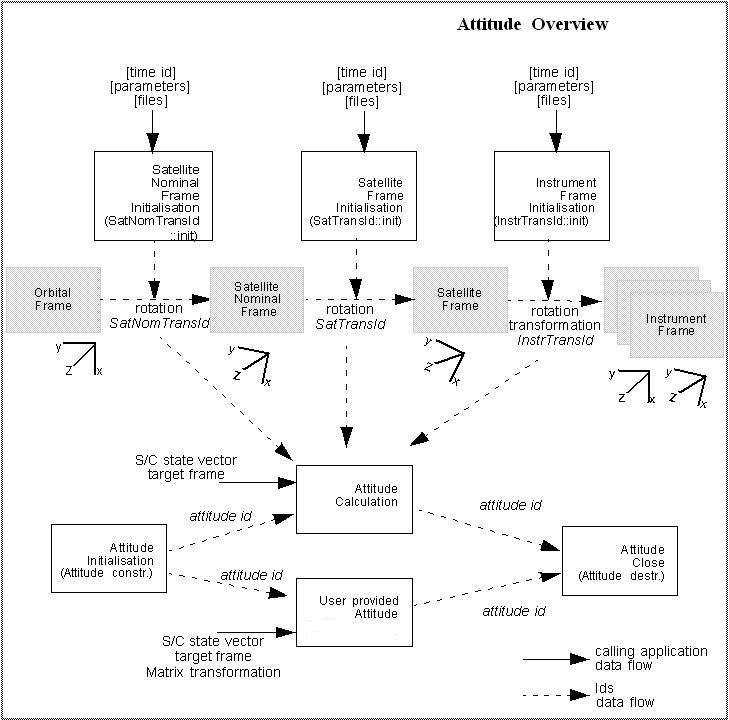
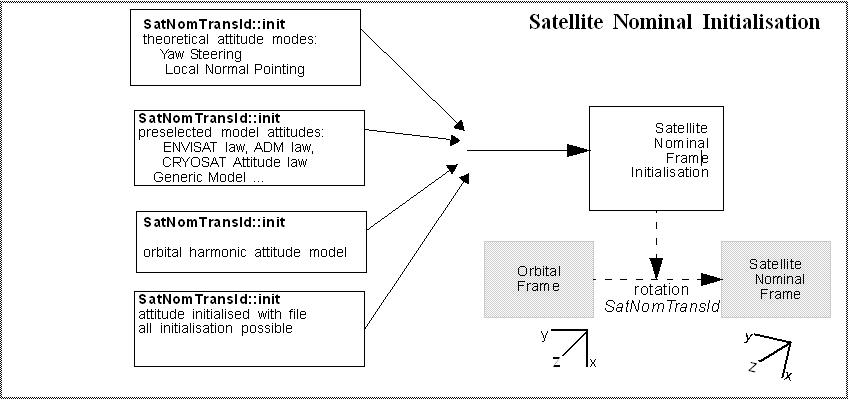
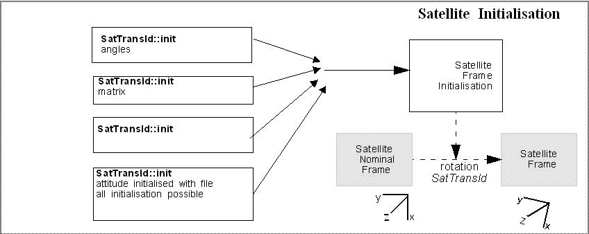
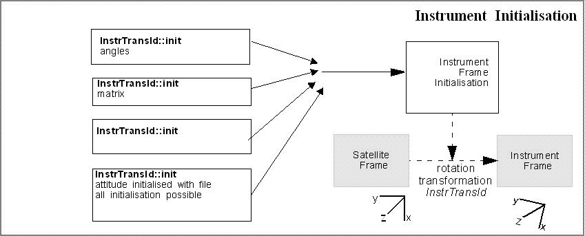
Each different transformation can be initialised with different models:
The following figure shows the tipical data flow for the geolocation routines functions. First, the attitude should be calculated, and, if needed, the refraction and Digital Elevation Models initialised.
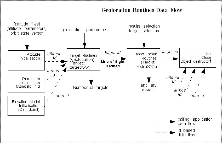
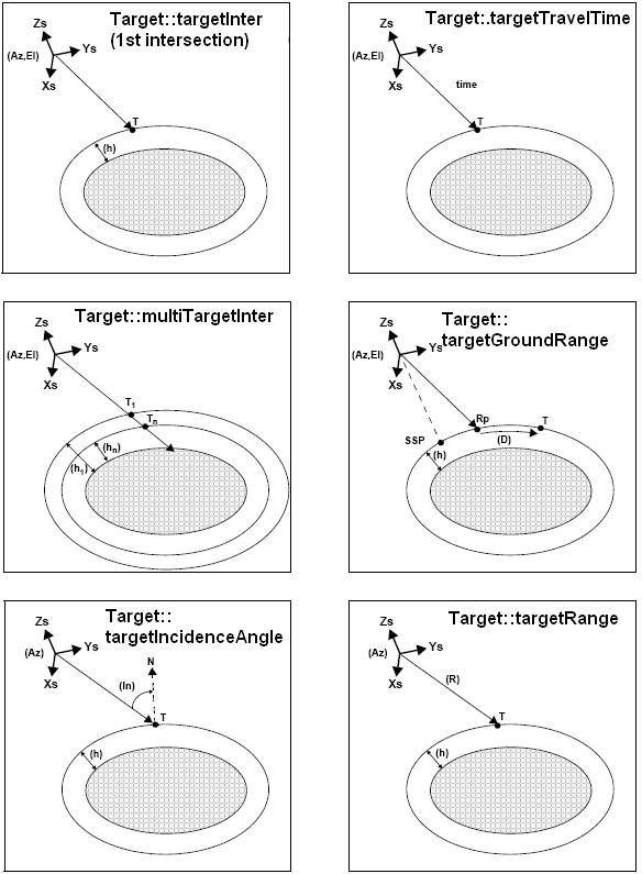
The table below and the diagrams on the next pages describe the various Target.targetXXX methods.
| Target.targetXXX method | Description | |
|---|---|---|
| Target.targetInter / Target.multiTargetInter | It calculates the intersection point(s) of the line of sight defined by an elevation and an azimuth angle expressed in the input Attitude frame, with a surface(s) located at a certain geodetic altitude(s) over the Earth. | |
| Target.targetTravelTime / Target.multiTargetTravelTime | It calculates the point of the line or sight from the satellite (defined by an elevation and an azimuth angle expressed in the selected Attitude Frame) at a given travel time(s) along the (curved) line of sight. | |
| Target.targetGroundRange | It calculates the location of a point that is placed on a surface at a certain geodetic altitude over the Earth, that lays on the plane defined by theS/C position, the nadir and a reference point, and that is at a certain distance or ground range measured along that surface from that reference point. This reference point is calculated being the intersection of the previous surface with the line of sight defined by an elevation and azimuth angle in the input Attitude coordinate system. | |
| Target.targetIncidenceAngle | It calculates the location of a point that is placed on a surface at a certain geodetic altitude over the Earth and that is seen from the S/C on a line of sight that forms a certain azimuth angle in the input Attitude frame and that intersects that surface with a certain incidence angle. | |
| Target.targetRange | It calculates the location of a point that is placed on a surface at a certain geodetic altitude over the Earth, that is seen from the S/C on a line of sight that forms a certain azimuth angle in the input Attitude frame, and that is at a certain range or slant-range from the S/C. | |
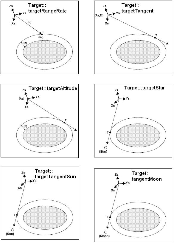
| Target.targetRangeRate | It calculates the location of a point that is placed on a surface at a certain geodetic altitude over the Earth, that is at a certain range from S/C, and whose associated Earth-fixed target has a certain range-rate value. | |
| Target.targetTangent | It calculates the location of the tangent point over the Earth that is located on the line of sight defined by an elevation and azimuth angles expressed in the input Attitude frame. | |
| Target.targetAltitude | It calculates the location of the tangent point over the Earth that is located on a surface at a certain geodetic altitude over the Earth and that is on a line of sight that forms a certain azimuth angle in the input Attitude frame. | |
| Target.targetStar | It calculates the location of the tangent point over the Earth that is located on the line of sight that points to a star defined by its right ascension and declination coordinates. | |
| Target.targetGeneric | The cartesian state vector of the target is taken as an input. | |
| Target.targetTangentSun | It calculates the location of the tangent point over the Earth that is located on the line of sight that points to the Sun | |
| Target.targetTangentMoon | It calculates the location of the tangent point over the Earth that is located on the line of sight that points to the Moon | |
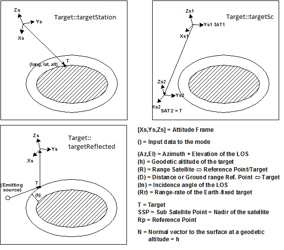
| Target.targetStation | It calculates the most relevant observation parameters of the link between the satellite and a ground station | |
| Target.targetSc | It calculates the most relevant observation parameters of the link between one source satellite and anothr target satellite. |
As it can be seen from the list of functions, there are some functions that calculate several targets (Target.multiTargetXXX). The number of targets found by the functions is stored in the Target object. In addition to these "user" targets, two other categories of targets can be defined, "LOS" targets and "DEM" targets.
The idea is to get information about all the ray path points computed by a specific target routine along the Line of Sight (LOS) trajectory. For every target method, the Target parameter numLosTarget will store the number of points in the path. It applies when the variable "targetType" is equal to XPCFI_LOS_TARGET_TYPE.
A DEM Target is defined as the intersection of a line of sight with the Earth Surface defined using a digital elevation model (DEM).
A DEM Target is calculated using as line of sight the LOS targets that has been computed previously with a target routine (Note that such LOS consist in a polygonal line, no necessarily a straight line). Consequently, to get a DEM target it is neccessary to follow these steps:
The digital elevation model of the Earth consists in a set of points defining a grid for which a measure of the altitude over the Earth reference elipsoid is given. The altitude of the points within each cell of the grid is computed by the CFI using a bilinear interpolation with the points of the corner of the cell. Details about the bilinear algorithm used to compute the intersection can be seen in [LOS_ALG].[LOS_ALG]
When the light propagation model is enabled, the target functions keep into account the time spent by a generic signal travelling at the speed of light to:
Two distinct times are considered:
dT is calculated as the light travel time from the satellite to target calculated with dT=0. When the light propagation model is not activated, it is assumed dT=0, therefore target and satellite are considered at the same time T.
According to the definitions above, the Line of Sight (LOS) can be defined as the segment joining satellite and target at their correspondent times.
For the following functions the calculation method is slightly different:
Target geometric properties (returned by the extra functions) are evaluated considering the two distinct times, for example:
Following figure shows an example using the Target.targetInter function.
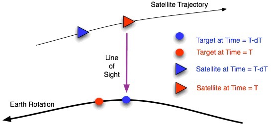
The light propagation mode is set to RECEIVER and input azimuth,elevation are 0, 90 deg (assuming a local normal pointing). The signal is emitted by the target at time T-dT (blue point, let’s assume at geodetic co-ordinates (lon,lat,h) and EF co-ordinates (X,Y,Z) ) and is received by the satellite at time T (red triangle). Due to Earth rotation, at time T the observed target has moved to the red point.
Here are some examples of results from Target.extra… functions:
The same results are given by the Target.extra… functions if the Target.targetGeneric is called with input target at EF co-ordinates (X,Y,Z) and velocity set to zero.
To activate the light propagation mode the modelId object must be initialized as follow:
for TRANSMITTER mode:
long mode;
vector<long> models;
mode = XLCFI_MODEL_CONFIG;
models.clear();
...
models.push_back(XLCFI_MODEL_LIGHT_PROPAGATION_TRANSMITTER);
modelId = new ModelId(mode, models);
for RECEIVER mode:
long mode;
vector<long> models;
mode = XLCFI_MODEL_CONFIG;
models.clear();
...
models.push_back(XLCFI_MODEL_LIGHT_PROPAGATION_RECEIVER);
modelId = new ModelId(mode, models);
For a detailed description of the installation of any CFI library, please refer to [GEN_SUM].
Note that to use the POINTING software library, the following other CFI software libraries are required:
Third party libraries:
In order to improve run-time performance, some methods (e.g. Target.extraListVector, Target.extraListMain, Target.extraListAux, Target.extraListEfTarget, Target.extraListTargetToSun, Target.extraListTargetToMoon,Target.extraListSpecularReflection) perform their computations in multi-threading mode. The multi-threading code of the Pointing functions uses the OpenMP API (see http://en.wikipedia.org/wiki/OpenMP). OpenMP is not supported in the clang compiler, therefore such functions work in single-thread mode in MacOS.
To use the CFI ORBIT software library in an user application, that application must import the classes that are going to be used. To do this, it must be taken into account that all CFI classes are part of EECFI package. For instance, to import class OneCfiClass:
For Java to find the classes, the jar files where they are defined must be included in the CLASSPATH environment variable. For Pointing library, CLASSPATH must be something like:
where jar_directory is the directory where the jar files are stored.
CFI libraries call C++ native methods. These methods are defined in dynamic libraries, which name and extension depend on the operating system:
If these libraries are stored in cfi_lib_dir, this directory must be included in the path where the system looks for dynamic libraries (LD_LIBRARY_PATH in LINUX and SOLARIS, DYLD_LIBRARY_PATH in MAC systems, PATH in WINDOWS sytem).
Every CFI library has defined constant values that can be used as input for several methods of the classes. They are grouped in a class with the name EnumLibrary. To use them, a static import is recommended:
so the constants can be used directly, without prefixing with package name and class name.
You can consult the constants available for this library here.
The error management in Java POINTING is made throw exceptions, that is, if any error is produced, an exception of type CfiError is thrown and it must be catched putting the code inside a try-catch block.
See [GEN_SUM] to know more about how to handle the CFI errors. For a descripton about the CfiError class and its methods, see [EE_COMMON_SUM].
 1.7.1
1.7.1