Earth Observation Mission CFI Software Pointing Software User Manual for JAVA |
Earth Observation Mission CFI Software Pointing Software User Manual for JAVA |
Class for storing the Satellite Nominal Attitude configuration parameters. More...
Public Member Functions | |
| SatNomTransId () | |
| Empty Class finalructor. | |
| native void | init (long aocsModel) throws CfiError |
| Initialise using AOCS model. | |
| native void | init (long model, final Vector< Double > modelParams) throws CfiError |
| Initialise satellite nominal attitude model for a given satellite. | |
| native void | init (long angleType, final Vector< Long > harmTypePitch, final Vector< Long > harmTypeRoll, final Vector< Long > harmTypeYaw, final Vector< Double > harmCoeffPitch, final Vector< Double > harmCoeffRoll, final Vector< Double > harmCoeffYaw) throws CfiError |
| Initialise satellite orbital to satellite nominal attitude mispointing angles for a given satellite with harmonics. | |
| native void | init (final TimeCorrelation timeId, final Vector< String > files, long timeInitMode, long timeRef, double time0, double time1) throws CfiError |
| Initialise satellite nominal attitude angles for a given satellite reading values from the attitude files. | |
| native long | getAOCS () throws CfiError |
| Get AOCS parameters. | |
| native void | setAOCS (long aocsModel) throws CfiError |
| Change initialisation AOCS parameters from the object. | |
| native ParamModel | getParam () throws CfiError |
| Get initialisation parameters of object. | |
| native void | setParam (final ParamModel paramModel) throws CfiError |
| Change initialisation parameters of the object. | |
| native HarmonicModel | getHarmonic () throws CfiError |
| Get harmonic parameters of object. | |
| native void | setHarmonic (final HarmonicModel harmModel) throws CfiError |
| Change harmonic parameters of the object. | |
| native AttFileModel | getFile () throws CfiError |
| Get file data of object. | |
| native void | setFile (final AttFileModel fileModel) throws CfiError |
| Change initialisation file data of the object. | |
| native void | setAzElDefinition (final AzElDefinition azElDef) throws CfiError |
| Set azimuth/elevation definition. | |
| native SatId | satId () |
| Return satellite id. | |
Class for storing the Satellite Nominal Attitude configuration parameters.
| EECFI.SatNomTransId.SatNomTransId | ( | ) |
Empty Class finalructor.
| long EECFI.SatNomTransId::getAOCS | ( | ) | throws CfiError |
Get AOCS parameters.
| AttFileModel EECFI.SatNomTransId::getFile | ( | ) | throws CfiError |
Get file data of object.
| HarmonicModel EECFI.SatNomTransId::getHarmonic | ( | ) | throws CfiError |
Get harmonic parameters of object.
| ParamModel EECFI.SatNomTransId::getParam | ( | ) | throws CfiError |
Get initialisation parameters of object.
| void EECFI.SatNomTransId::init | ( | long | model, | |
| final Vector< Double > | modelParams | |||
| ) | throws CfiError |
Initialise satellite nominal attitude model for a given satellite.
| model | Model (SatNominalAttModelEnum). | |||||||||||||||||||||||||||||||||||||||||||||||||||||||||||||||||||||||||||||||||||||||||||||||||||||||
| modelParams | Vector with parameters of the corresponding model.
Generic Model descriptionThe generic model builds the reference frames from the specified direction vectors.The model parameters are:
** Sun-Fixed Reference Frame
|
| void EECFI.SatNomTransId::init | ( | long | angleType, | |
| final Vector< Long > | harmTypePitch, | |||
| final Vector< Long > | harmTypeRoll, | |||
| final Vector< Long > | harmTypeYaw, | |||
| final Vector< Double > | harmCoefPitch, | |||
| final Vector< Double > | harmCoefRoll, | |||
| final Vector< Double > | harmCoefYaw | |||
| ) | throws CfiError |
Initialise satellite orbital to satellite nominal attitude mispointing angles for a given satellite with harmonics.
The Attitude.compute and Attitude.changeFrame functions will then compute the values as follows:
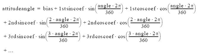
| angleType | Type of angle (given by PointingAngleTypeEnum). | |
| harmTypePitch | Type of coefficients:
. | |
| harmTypeRoll | Type of coefficients (bias, sinus, cosinus). | |
| harmTypeYaw | Type of coefficients (bias, sinus, cosinus). | |
| harmCoefPitch | Bias, sinus and cosinus coefficients for the pitch angle. | |
| harmCoefRoll | Bias, sinus and cosinus coefficients for the roll angle. | |
| harmCoefYaw | Bias, sinus and cosinus coefficients for the yaw angle. |
| void EECFI.SatNomTransId::init | ( | final TimeCorrelation | timeId, | |
| final Vector< String > | files, | |||
| long | timeInitMode, | |||
| long | timeRef, | |||
| double | time0, | |||
| double | time1 | |||
| ) | throws CfiError |
Initialise satellite nominal attitude angles for a given satellite reading values from the attitude files.
| void EECFI.SatNomTransId::init | ( | long | aocsModel | ) | throws CfiError |
Initialise using AOCS model.
| aocsModel | AOCS model (SatNominalAttAocsModeEnum). |
| SatId EECFI.SatNomTransId::satId | ( | ) |
Return satellite id.
| void EECFI.SatNomTransId::setAOCS | ( | long | aocsModel | ) | throws CfiError |
Change initialisation AOCS parameters from the object.
| aocsModel | AOCS model. |
| void EECFI.SatNomTransId::setAzElDefinition | ( | final AzElDefinition | azElDef | ) | throws CfiError |
Set azimuth/elevation definition.
| azElDef | Definition of azimuth and elevation. |
| void EECFI.SatNomTransId::setFile | ( | final AttFileModel | fileModel | ) | throws CfiError |
Change initialisation file data of the object.
| fileModel | File model data. |
| void EECFI.SatNomTransId::setHarmonic | ( | final HarmonicModel | harmModel | ) | throws CfiError |
Change harmonic parameters of the object.
| harmModel | Harmonic model data. |
| void EECFI.SatNomTransId::setParam | ( | final ParamModel | paramModel | ) | throws CfiError |
Change initialisation parameters of the object.
| paramModel | Parameters of model. |
 1.7.1
1.7.1