DEIMOS
Earth Observation Mission CFI Software
Visibility Software User Manual
ESA

EECFI::Swath Class Reference

Class to make operations involving a swath for zone and station visibility. More...

Inheritance diagram for EECFI::Swath:
EECFI::CfiClass

List of all members.

Public Member Functions

 Swath ()
 Empty Class constructor.
 Swath (const OrbitId &orbitId, string swathFileName) throw (CfiError)
 Class constructor with parameters for STF file.
 Swath (const OrbitId &orbitId, long orbitNum, string swathFileName) throw (CfiError)
 Class constructor with parameters for SDF file.
 ~Swath () throw (CfiError)
 Class destructor.
void set (const OrbitId &orbitId, string swathFileName) throw (CfiError)
 Set values of parameters with STF file.
void set (const OrbitId &orbitId, long orbitNum, string swathFileName) throw (CfiError)
 Set values of parameterswith SDF file.
void set (const AtmosId &atmosId) throw (CfiError)
 Set Atmosphere Id, necessary for swath generation.
VisibilityList zoneVisTime (long startOrbit, long stopOrbit, string zoneId, string zoneDBFile, long projection, double minDuration) throw (CfiError)
 Calculate zone visibility segments using a zone database.
VisibilityList zoneVisTime (long startOrbit, long stopOrbit, long projection, const ZoneRec &zoneRec, double minDuration) throw (CfiError)
 Calculate zone visibility segments using a zone rec.
VisibilityList zoneVisTime (long startOrbit, long stopOrbit, long projection, const StfFile &stfFile, const ZoneRec &zoneRec, double minDuration) throw (CfiError)
 Calculate zone visibility segments using a STF object and ZoneRec.
VisibilityList stationVisTime (long startOrbit, long stopOrbit, string staId, string staDBFile, long mask, double aosElevation, double losElevation, double minDuration) throw (CfiError)
 Calculate the visibility segments for which a satellite is visible from a ground station.
VisibilityList stationVisTime (long startOrbit, long stopOrbit, const StfFile &stfFile, const StationRec &staRec, long mask, double aosElevation, double losElevation, double minDuration) throw (CfiError)
 Calculate the visibility segments for which a satellite is visible from a ground station.
VisibilityList scVisTime (const SatNomTransId &satNomTransId1, const SatTransId &satTransId1, const InstrTransId &instrTransId1, long startOrbit, long stopOrbit, const OrbitId &orbitId2, const SatNomTransId &satNomTransId2, const SatTransId &satTransId2, const InstrTransId &instrTransId2, LinkData &linkData, double minDuration) throw (CfiError)
VisibilityList multiZonesVisTime (long startOrbit, long stopOrbit, const vector< string > &zoneId, string zoneDBFile, const vector< long > &projection, const vector< ZoneRec > &zoneRec, double minDuration, bool extraInfoFlag) throw (CfiError)
 Calculates visibility segments for which the swath intersects a set of zones on the Earth ellipsoid.
VisibilityList multiStationsVisTime (long startOrbit, long stopOrbit, const vector< string > &staId, string staDBFile, const vector< double > &aosElevation, const vector< double > &losElevation, const vector< long > &mask, double minDuration, bool extraInfoFlag) throw (CfiError)
 Calculates visibility segments for which a satellite is visible from a set of ground stations.
vector< VisibilityListmapping (long startOrbit, long stopOrbit, string zoneId, string zoneDBFile, long projection) throw (CfiError)
 Computes groups of visibility segments that cover the visiblity of a zone read from a database.
vector< VisibilityListmapping (long startOrbit, long stopOrbit, long projection, const ZoneRec &zoneRec) throw (CfiError)
 Computes groups of visibility segments that cover the visiblity of a given zone.
string genSwath (long requestedOrbit, string dirName, string swathFile, string fileClass, long versionNumber, string fhSystem) throw (CfiError)
 Generate a swath template file using the SDF file.
StfFilegenSwath (long requestedOrbit, const SdfFile &sdfFile) throw (CfiError)
 Generate a STFFile object using the object SdfFile.
vector< GeodeticgetPos (const StfFile &stfFile, const ANXTime &anxTime) throw (CfiError)
 Gets the location of a swath at a given ANXTime.
string genScf (string instrument, const VisibilityList &visList, const vector< ScfAppear > &scfApp, string dirName, string scfFileName, string fileClass, long versionNumber, string fhSystem) throw (CfiError)
 Generate a swath control file.

Detailed Description

Class to make operations involving a swath for zone and station visibility.


Constructor & Destructor Documentation

EECFI::Swath::Swath (  ) 

Empty Class constructor.

EECFI::Swath::Swath ( const OrbitId orbitId,
string  swathFileName 
) throw (CfiError)

Class constructor with parameters for STF file.

Parameters:
orbitId Orbit Id.
swathFileName Swath template filename (path).
EECFI::Swath::Swath ( const OrbitId orbitId,
long  orbitNum,
string  swathFileName 
) throw (CfiError)

Class constructor with parameters for SDF file.

Parameters:
orbitId Orbit Id.
orbitNum Swath points are generated every "orbitNum" orbits.
swathFileName Swath definition filename (path).
EECFI::Swath::~Swath (  )  throw (CfiError)

Class destructor.


Member Function Documentation

string EECFI::Swath::genScf ( string  instrument,
const VisibilityList visList,
const vector< ScfAppear > &  scfApp,
string  dirName,
string  scfFileName,
string  fileClass,
long  versionNumber,
string  fhSystem 
) throw (CfiError)

Generate a swath control file.

This file contains a list of visibility segments together with some features linked to the segment that are used for the visualisation of the segment in the ESOV tool.

Parameters:
instrument Instrument name.
visList Visibility segments.
scfApp Array with the structures containing the appearance for every segment.
dirName Directory where resulting STF is written.
scfFileName Name for output swath file. If empty ("") the software will generate the name according to file name specifications.
fileClass File class for output file.
versionNumber Version number of output file. Allowed range: >=1.
fhSystem System field of the output fixed header.
Returns:
Name of the file generated.

References EECFI::CfiError::addMsg().

string EECFI::Swath::genSwath ( long  requestedOrbit,
string  dirName,
string  swathFile,
string  fileClass,
long  versionNumber,
string  fhSystem 
) throw (CfiError)

Generate a swath template file using the SDF file.

The atmospheric and refraction model is determined by the AtmosId object. If AtmosId is not set, refraction will not be considered

Overview

The Swath::genSwath function generates for the different instrument modes the corresponding instrument swath template file. These template files define the swaths to be used in the segment calculation routines of EO_VISIBILITY.
The selection of the algorithm to compute the swath points depends on the parameters of the corresponding swath definition found in the instrument swath definition file. The swath point type (geodetic or inertial) and the algorithm to be used is deduced from the geometry and other instrument dependent parameters:
Swath geometry definition (algorithm)
Geometry
Algorithm description Swath point type
Pointing_Geometry (azimuth, elevation, altitude) Swath point computed with Target::targetInter with that azimuth, elevation and altitude Geodetic
Distance_Geometry (azimuth, elevation, altitude, distance) Swath point computed with Target::targetGroundRange with that azimuth, elevation, altitude and distance Geodetic
Limb_Geometry (azimuth and altitude) Swath point computed with Target::targetAltitude with that azimuth and altitude Geodetic
Inertial_Geometry (azimuth and altitude) Swath point computed with Target::targetAltitude with that azimuth and altitude. The swath point is the RA and Declination of the target. Inertial
Sub_Satellite_Geometry (no parameters) Computation of the sub-satellite point Geodetic
ASAR_Geometry (azimuth, elevation, altitude) Specific algorithm for the three swath points for ASAR instrument in Envisat. Geodetic
The instrument swath template file, consists of a header which contains the altitude range of the swath. The data block contains n locations of the swath (between 50 and 6000, typically 1200) equally spread in time along one orbit. Every swath location contains a list of m points of the instantaneous swath (m>=1). For a description of the swath configuration see Swath::zoneVisTime documentation.
For Earth-fixed swaths, the location is given in longitude and latitude, in degrees, for the orbit with a longitude of ascending node of 0.0 degrees. For Inertial swaths, the location is the direction in inertial space (True of Date) in Right Ascension and Declination, in degrees, for the orbit with a Right Ascension of Ascending Node of 0.0 degrees.
The instrument swath template files are only dependent on:
  • The instrument swath definition file
  • The requested orbit number
  • The orbit definition (orbitId).
Parameters:
requestedOrbit Absolute orbit for which the instrument swath template file will be calculated.
dirName Directory where the resulting STF is written (current directory used ir empty string).
swathFile Name for output swath file (if empty, the name will be generated according to file name specifications).
fileClass File class for output swath file.
versionNumber Version number for output swath file. Allowed range: >=1.
fhSystem System field of the output swath file fixed header.
Returns:
Name of the file generated.

References EECFI::CfiError::addMsg().

StfFile * EECFI::Swath::genSwath ( long  requestedOrbit,
const SdfFile sdfFile 
) throw (CfiError)

Generate a STFFile object using the object SdfFile.

OrbitId must be set. The atmospheric and refraction model is determined by the AtmosId object. If AtmosId is not set, refraction will not be considered.

Parameters:
requestedOrbit Absolute orbit for which the instrument swath template file will be calculated.
sdfFile Swath Definition File object. It must have been read.
Returns:
Pointer to StfFile object created.

References EECFI::CfiError::addMsg().

vector< Geodetic > EECFI::Swath::getPos ( const StfFile stfFile,
const ANXTime anxTime 
) throw (CfiError)

Gets the location of a swath at a given ANXTime.

Parameters:
stfFile Object with Swath Template File read.
anxTime Absolute orbit and time where position wants to be calculated.
Returns:
Coordinates of the points of the swath.

References EECFI::CfiError::addMsg(), EECFI::Geodetic::alt, EECFI::Geodetic::altDer, EECFI::Geodetic::deriv, EECFI::Geodetic::lat, EECFI::Geodetic::latDer, EECFI::Geodetic::lon, and EECFI::Geodetic::lonDer.

vector< VisibilityList > EECFI::Swath::mapping ( long  startOrbit,
long  stopOrbit,
string  zoneId,
string  zoneDBFile,
long  projection 
) throw (CfiError)

Computes groups of visibility segments that cover the visiblity of a zone read from a database.

Overview

The function Swath::mapping returns groups of visibility segments of a zone within an orbit range introduced by the user. These groups, or mappings, contain a minimum number of time segments needed to cover the zone completely, and fulfil the following conditions:
  • Each mapping only contains ascending or descending segments.
  • The segments are ordered by the track number.
  • Mappings with one segment will be returned if it covers completely the zone.
  • A mapping is searched for each track with segments that only contains left/right coverage in the case of ascending/descending segments, and finishes with a track that only contains right/left coverage.
  • Incomplete mappings are not returned. This could happen if the number of orbits is insufficient to cover the zone.
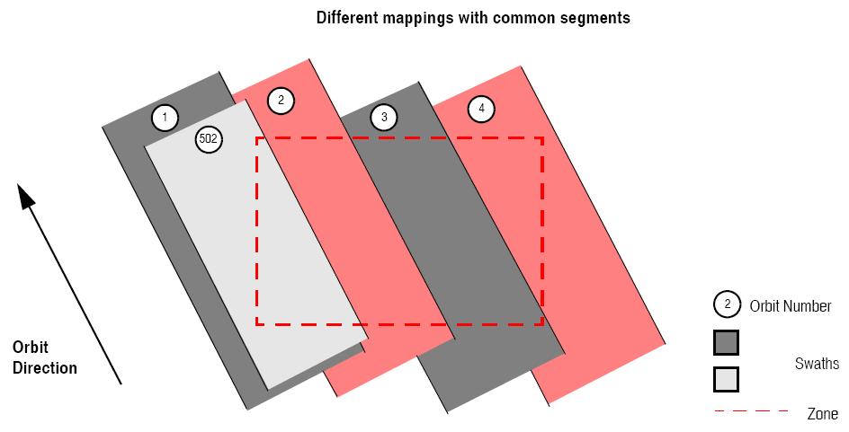
Note that different mappings could contain a subset of segments in common. For example in next figure there are two possible different mappings:
  • mapping 1: orbits 1, 2, 3, 4.
  • mapping 2: orbits 502, 2, 3, 4.
Different mappings with common segments
The time intervals used by Swath::mapping can be expressed in absolute or relative orbit numbers. This is valid for both:
  • input parameter: first and last orbit to be considered. To transform from relative to absolute orbits, RelANXTime::toAbsolute can be used.
  • output parameter: time segments with time expressed as {absolute orbit number, number of seconds since ANX, number of microseconds}
The Swath::mapping requires access to several data structures and files to produce its results:
  • the orbitId (OrbitId class) providing the orbital data. The orbitId can be initialized with the following data or files (see [ORBIT_SUM]):
    • data for an orbital change
    • Orbit scenario files
    • Predicted orbit files
    • Orbit Event Files
    • Restituted orbit files
    • DORIS Preliminary orbit files
    • DORIS Navigator files
  • the Instrument Swath File, excluding inertial swath files, describing the area seen by the relevant instrument all along the current orbit. The Swath data can be provided by:
    • A swath template file produced off-line by the EO_VISIBILITY library (Swath::genSwath function).
    • A swath definition file, describing the swath geometry. In this case the Swath::mapping generates the swath points for a number of orbits given by the user.
  • Zone Database File: just in case of using a zone from the data base.
Parameters:
startOrbit First absolute orbit, segment filter; segments will be filtered as from the beginning of first orbit. First Orbit for the orbit initialization will be used when absolute orbit is set to zero.
Allowed range: =0; or >=start_osf.
stopOrbit Last absolute orbit, segment filter. For orbitId initialized with orbital changes, when stopOrbit = 0 the stopOrbit will be set to the minimum value between:

  • the last orbit within the orbital change of the start_orbit.
  • startOrbit+cycle_length-1 (i.e. the input orbit range will be a complete cycle)

Allowed range: =0; or >=start_osf.

zoneId Identification of the zone, as defined in zoneDBFile.
zoneDBFile File name of the zone database file.
projection Projection used to define the polygon sides as straight lines (ProjectionEnum in VisibilityData.h).
Returns:
Vector of VisibilityList, one VisibilityList for each mappping found.
vector< VisibilityList > EECFI::Swath::mapping ( long  startOrbit,
long  stopOrbit,
long  projection,
const ZoneRec zoneRec 
) throw (CfiError)

Computes groups of visibility segments that cover the visiblity of a given zone.

Parameters:
startOrbit First absolute orbit, segment filter; segments will be filtered as from the beginning of first orbit. First Orbit for the orbit initialization will be used when absolute orbit is set to zero.
Allowed range: =0; or >=start_osf.
stopOrbit Last absolute orbit, segment filter. For orbitId initialized with orbital changes, when stopOrbit = 0 the stopOrbit will be set to the minimum value between:

  • the last orbit within the orbital change of the start_orbit.
  • startOrbit+cycle_length-1 (i.e. the input orbit range will be a complete cycle)

Allowed range: =0; or >=start_osf.

projection Projection used to define the polygon sides as straight lines (ProjectionEnum in VisibilityData.h).
zoneRec Zone definition.
Returns:
Vector of VisibilityList, one VisibilityList for each mappping found.
VisibilityList EECFI::Swath::multiStationsVisTime ( long  startOrbit,
long  stopOrbit,
const vector< string > &  staId,
string  staDBFile,
const vector< double > &  aosElevation,
const vector< double > &  losElevation,
const vector< long > &  mask,
double  minDuration,
bool  extraInfoFlag 
) throw (CfiError)

Calculates visibility segments for which a satellite is visible from a set of ground stations.

Parameters:
startOrbit First absolute orbit, segment filter; segments will be filtered as from the beginning of first orbit. First Orbit for the orbit initialization will be used when absolute orbit is set to zero.
Allowed range: =0; or >=start_osf.
stopOrbit Last absolute orbit, segment filter. For orbitId initialized with orbital changes, when stopOrbit = 0 the stopOrbit will be set to the minimum value between:

  • the last orbit within the orbital change of the start_orbit.
  • startOrbit+cycle_length-1 (i.e. the input orbit range will be a complete cycle)

Allowed range: =0; or >=start_osf.

staId Identification of the stations, as defined in staDBFile.
staDBFile File name of the station database file.
mask Mask used to define visibility (MaskEnum in VisibilityData.h).
aosElevation Minimum elevation to consider at AOS [deg]. Allowed range: >=0.0.
losElevation Maximum elevation to consider at LOS [deg]. Allowed range: >=0.0 ; <=aosElevation.
minDuration Minimum duration for segments; only segments with a duration longer than minDuration will be given as output [s]. Allowed range: >=0.
extraInfoFlag If true, numberOfStations and stationsInSegment are calculated (see VisibilitySegment.h).
Returns:
Visibility segments.

References EECFI::CfiError::addMsg().

VisibilityList EECFI::Swath::multiZonesVisTime ( long  startOrbit,
long  stopOrbit,
const vector< string > &  zoneId,
string  zoneDBFile,
const vector< long > &  projection,
const vector< ZoneRec > &  zoneRec,
double  minDuration,
bool  extraInfoFlag 
) throw (CfiError)

Calculates visibility segments for which the swath intersects a set of zones on the Earth ellipsoid.

Parameters:
startOrbit First absolute orbit, segment filter; segments will be filtered as from the beginning of first orbit. First Orbit for the orbit initialization will be used when absolute orbit is set to zero.
Allowed range: =0; or >=start_osf.
stopOrbit Last absolute orbit, segment filter. For orbitId initialized with orbital changes, when stopOrbit = 0 the stopOrbit will be set to the minimum value between:

  • the last orbit within the orbital change of the start_orbit.
  • startOrbit+cycle_length-1 (i.e. the input orbit range will be a complete cycle)

Allowed range: =0; or >=start_osf.

zoneId Identification of the zones (it must be one for every zone, not only the ones read from database, but the stations read from database must be placed first in vector).
zoneDBFile File name of the zone database file.
projection Projection used to define the polygon sides as straight lines (ProjectionEnum in VisibilityData.h).
zoneRec Zones definition.
minDuration Minimum duration for segments; only segments with a duration longer than minDuration will be given as output [s]. Allowed range: >=0.
extraInfoFlag If true, numberOfZones, zonesInSegment and multiCoverage are calculated (see VisibilitySegment.h).
Returns:
Visibility segments.

References EECFI::CfiError::addMsg().

VisibilityList EECFI::Swath::scVisTime ( const SatNomTransId satNomTransId1,
const SatTransId satTransId1,
const InstrTransId instrTransId1,
long  startOrbit,
long  stopOrbit,
const OrbitId orbitId2,
const SatNomTransId satNomTransId2,
const SatTransId satTransId2,
const InstrTransId instrTransId2,
LinkData linkData,
double  minDuration 
) throw (CfiError)

Calculates the visibility segments for which a Communication Terminal of a target satellite is visible from a Communication Terminal of a source satellite.

Overview

The Swath::scVisTime method computes all the orbital segments for which Communication Terminal of a target satellite (LEO or GEO) is visible from Communication Terminal of a source satellite (LEO).
An orbital segment is a time interval along the orbit, defined by start and stop times expressed as seconds elapsed since the ascending node crossing.
Swath::scVisTime requires access to the orbitId (OrbitId class) providing the orbital data of both satellites. For orbitId initialization please refer to [ORBIT_SUM].
The time intervals used by Swath::scVisTime are expressed in absolute orbit numbers. To transform from relative to absolute orbits, RelANXTime::toAbsolute can be used. This is valid for both:
  • input parameter "Orbit Range": first and last orbit to be considered.
  • output parameter "Target Satellite Visibility Segments": time segments with time expressed as {absolute orbit number , number of seconds since ANX, number of microseconds}
The output segments will be ordered chronologically.
Users who need to use processing times must make use of the conversion routines provided in EO_ORBIT ANXTime class (ANXTime::timeToOrbit and ANXTime::orbitToTime methods).
The Swath::scVisTime function considers the following sources of occultation, which can be configured through xv_link_data input struct:
  • Earth plus a minimum tangent height.
  • Satellite inclusive and exclusive masks, which are zones of azimuth and elevation where visibility is possible (inclusive mask) or not possible (exclusive mask). With this masks all the restrictions (mechanical or of any type) must be simulated.

Notes about definition of masks:
  • The masks are defined as closed zones.
  • These zones are defined in the input LinkData object with arrays of azimuth and elevation points that define a polygon in the azimuth-elevation plane (last point in array is closed with first point in array internally).
  • It must be distinguished between azimuth = 0. deg and azimuth = 360. deg, since they are considered different in the azimuth-elevation plane; this has been done to make the definition of masks easier.
Parameters:
satNomTransId1 Satellite nominal attitude of source satellite.
satTransId1 Satellite attitude of source satellite.
instrTransId1 Instrument nominal attitude of source satellite.
startOrbit First absolute orbit, segment filter; segments will be filtered as from the beginning of first orbit. First Orbit for the orbit initialization will be used when absolute orbit is set to zero.
Allowed range: =0; or >=start_osf.
stopOrbit Last absolute orbit, segment filter. For orbitId initialized with orbital changes, when stopOrbit = 0 the stopOrbit will be set to the minimum value between:

  • the last orbit within the orbital change of the start_orbit.
  • startOrbit+cycle_length-1 (i.e. the input orbit range will be a complete cycle)

Allowed range: =0; or >=start_osf.

satNomTransId2 Satellite nominal attitude of target satellite.
satTransId2 Satellite attitude of target satellite.
instrTransId2 Instrument nominal attitude of target satellite.
linkData Link data between both satellites. Minimum tangent height and masks for visibility are configured.
minDuration Minimum duration for segments; only segments with a duration longer than minDuration will be given as output [s]. Allowed range: >=0.
Returns:
Visibility segments.

References EECFI::CfiError::addMsg(), EECFI::ANXTime::microseconds, EECFI::ANXTime::orbit, EECFI::ANXTime::seconds, EECFI::TimeSegment::start, and EECFI::TimeSegment::stop.

void EECFI::Swath::set ( const OrbitId orbitId,
long  orbitNum,
string  swathFileName 
) throw (CfiError)

Set values of parameterswith SDF file.

Parameters:
orbitId Orbit Id.
orbitNum Swath points are generated every "orbitNum" orbits.
swathFileName Swath definition filename (path).

References EECFI::CfiError::addMsg().

void EECFI::Swath::set ( const OrbitId orbitId,
string  swathFileName 
) throw (CfiError)

Set values of parameters with STF file.

Parameters:
orbitId Orbit Id.
swathFileName Swath template filename (path).
void EECFI::Swath::set ( const AtmosId atmosId  )  throw (CfiError)

Set Atmosphere Id, necessary for swath generation.

Parameters:
atmosId Atmosphere Id. The AtmosId object determines the atmospheric and refraction model to be used in the Swath generation
VisibilityList EECFI::Swath::stationVisTime ( long  startOrbit,
long  stopOrbit,
const StfFile stfFile,
const StationRec staRec,
long  mask,
double  aosElevation,
double  losElevation,
double  minDuration 
) throw (CfiError)

Calculate the visibility segments for which a satellite is visible from a ground station.

Parameters:
startOrbit First absolute orbit, segment filter; segments will be filtered as from the beginning of first orbit. First Orbit for the orbit initialization will be used when absolute orbit is set to zero.
Allowed range: =0; or >=start_osf.
stopOrbit Last absolute orbit, segment filter. For orbitId initialized with orbital changes, when stopOrbit = 0 the stopOrbit will be set to the minimum value between:

  • the last orbit within the orbital change of the start_orbit.
  • startOrbit+cycle_length-1 (i.e. the input orbit range will be a complete cycle)

Allowed range: =0; or >=start_osf.

stfFile StfFile object with STF information. File must have been read.
staRec Station data.
mask Mask used to define visibility (MaskEnum in VisibilityData.h).
aosElevation Minimum elevation to consider at AOS [deg]. Allowed range: >=0.0.
losElevation Maximum elevation to consider at LOS [deg]. Allowed range: >=0.0 ; <=aosElevation.
minDuration Minimum duration for segments; only segments with a duration longer than minDuration will be given as output [s]. Allowed range: >=0.
Returns:
Visibility segments.

References EECFI::CfiError::addMsg(), EECFI::ANXTime::microseconds, EECFI::ANXTime::orbit, EECFI::ANXTime::seconds, EECFI::TimeSegment::start, and EECFI::TimeSegment::stop.

VisibilityList EECFI::Swath::stationVisTime ( long  startOrbit,
long  stopOrbit,
string  staId,
string  staDBFile,
long  mask,
double  aosElevation,
double  losElevation,
double  minDuration 
) throw (CfiError)

Calculate the visibility segments for which a satellite is visible from a ground station.

Overview

The Swath::stationVisTime function computes ground station visibility segments, the orbital segments for which the satellite is visible from a ground station located at the surface of the Earth.
An orbital segment is a time interval along the orbit, defined by start and stop times expressed as seconds elapsed since the ascending node crossing.
In addition, Swath::stationVisTime calculates for every visibility segment the time of zero-doppler (i.e. the time at which the range-rate to the station is zero).
Swath::stationVisTime requires access to several data structures and files to produce its results:
  • the orbitId (OrbitId class) providing the orbital data. The orbitId can be initialized with the following data and files, also for precise propagation if applicable (see [ORBIT_SUM]):
    • data for an orbital change
    • Orbit scenario files
    • Predicted orbit files
    • Orbit Event Files
    • Restituted orbit files
    • DORIS Preliminary orbit files
    • DORIS Navigator files
    • TLE files
  • the Instrument Swath File, describing the area seen by the relevant instrument all along the current orbit. The Swath data can be provided by:
    • A swath template file produced off-line by the EO_VISIBILITY library (Swath::genSwath function).
    • A swath definition file, describing the swath geometry. In this case the Swath::stationVisTime generaes the swath points for a number of orbits given by the user.
  • The Station Database File, describing the location and the physical mask of each ground station.

The time intervals used by Swath::zoneVisTime are expressed in absolute orbit numbers. To transform from relative to absolute orbits, RelANXTime::toAbsolute can be used. This is valid for both:
  • input parameter "Orbit Range": first and last orbit to be considered.
  • output parameter "Station Visibility Segments": time segments with time expressed as {absolute orbit number , number of seconds since ANX, number of microseconds}
The output segments will be ordered chronologically.
Users who need to use processing times must make use of the conversion routines provided in EO_ORBIT ANXTime class (ANXTime::timeToOrbit and ANXTime::orbitToTime methods).
NOTE 1:If Swath::stationVisTime is used with a range of orbits that includes an orbital change (e.g. change in the repeat cycle or cycle length), the behaviour depends on the swath file introduced as input:
  • If a swath template file is used, Swath::stationVisTime automatically will ignore the orbits that do not correspond with the template file (i.e. no visibility segments will be generated for those orbits), since swath template file is generated from a reference orbit with a particular geometry, so it is not valid for a different geometry.
  • If a swath definition file is introduced, Swath::stationVisTime will perform the computations across orbital changes, and will return the visibility segments corresponding to the whole orbital range. Internally, swath template files valid for every orbital change are generated to perform the calculations.

NOTE 2:If a swath template file with the variable header tags Start_Validity_Range and Stop_Validity_Range is used as input, only the segments belonging to that orbit range will be returned.
Parameters:
startOrbit First absolute orbit, segment filter; segments will be filtered as from the beginning of first orbit. First Orbit for the orbit initialization will be used when absolute orbit is set to zero.
Allowed range: =0; or >=start_osf.
stopOrbit Last absolute orbit, segment filter. For orbitId initialized with orbital changes, when stopOrbit = 0 the stopOrbit will be set to the minimum value between:

  • the last orbit within the orbital change of the start_orbit.
  • startOrbit+cycle_length-1 (i.e. the input orbit range will be a complete cycle)

Allowed range: =0; or >=start_osf.

staId Identification of the station, as defined in staDBFile.
staDBFile File name of the station database file.
mask Mask used to define visibility (MaskEnum in VisibilityData.h).
aosElevation Minimum elevation to consider at AOS [deg]. Allowed range: >=0.0.
losElevation Maximum elevation to consider at LOS [deg]. Allowed range: >=0.0 ; <=aosElevation.
minDuration Minimum duration for segments; only segments with a duration longer than minDuration will be given as output [s]. Allowed range: >=0.
Returns:
Visibility segments.

References EECFI::CfiError::addMsg(), EECFI::ANXTime::microseconds, EECFI::ANXTime::orbit, EECFI::ANXTime::seconds, EECFI::TimeSegment::start, and EECFI::TimeSegment::stop.

VisibilityList EECFI::Swath::zoneVisTime ( long  startOrbit,
long  stopOrbit,
string  zoneId,
string  zoneDBFile,
long  projection,
double  minDuration 
) throw (CfiError)

Calculate zone visibility segments using a zone database.

Overview

The Swath::zoneVisTime method computes all the orbital segments for which a given instrument swath intercepts a user-defined zone at the surface of the Earth ellipsoid. An orbital segment is a time interval along the orbit, defined by start and stop times expressed as seconds (and microseconds) elapsed since the ascending node crossing. A user-defined zone can be:
  • a polygon specified by a set of latitude and longitude points
  • a circle specified by the centre latitude, longitude, and the diameter
Note that particular cases of the above can be used to define the zone as:
  • a point
  • a line
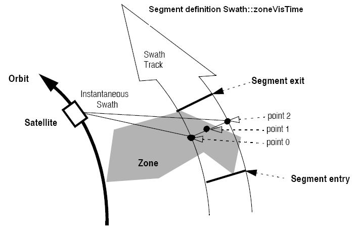
Segment Definition Swath::zoneVisTime

Swath::zoneVisTime requires access to several data structures and files to produce its results:
  • the orbitId (OrbitId object) providing the orbital data. The orbitId can be initialized with the following data or files, also for precise propagation if applicable (see [ORBIT_SUM]):
    • data for an orbital change
    • Orbit scenario files
    • Predicted orbit files
    • Orbit Event Files
    • Restituted orbit files
    • DORIS Preliminary orbit files
    • DORIS Navigator files
    • TLE files
  • the Instrument Swath File, excluding inertial swath files, describing the area seen by the relevant instrument all along the current orbit. The Swath data can be provided by:
    • A swath template file produced off-line by the EO_VISIBILITY library (Swath::genSwath method).
    • A swath definition file, describing the swath geometry. In this case the Swath::zoneVisTime generates the swath points for a number of orbits given by the user.
  • optionally, a Zone Database File, containing the zone description. The user can either specify a zone identifier referring to a zone in the file, or provide the zone parameters directly to Swath::zoneVisTime.
The time intervals used by Swath::zoneVisTime are expressed in absolute orbit numbers. To transform from relative to absolute orbits, RelANXTime::toAbsolute can be used. This is valid for both:
  • input parameter "Orbit Range": first and last orbit to be considered.
  • output parameter "Zone Visibility Segments": time segments with time expressed as {absolute orbit number, number of seconds since ascending node, number of microseconds}
The output segments will be the ordered chronologically.
Users who need to use processing times must make use of the conversion routines provided in EO_ORBIT ANXTime class (ANXTime::timeToOrbit and ANXTime::orbitToTime methods).
NOTE 1: If Swath::zoneVisTime is used with a range of orbits that includes an orbital change (e.g. change in the repeat cycle or cycle length), the behaviour depends on the swath file introduced as input: If a swath template file is used, Swath::zoneVisTime automatically will ignore the orbits that do not correspond with the template file (i.e. no visibility segments will be generated for those orbits), since swath template file is generated from a reference orbit with a particular geometry, so it is not valid for a different geometry. If a swath definition file is introduced, Swath::zoneVisTime will perform the computations across orbital changes, and will return the visibility segments corresponding to the whole orbital range. Internally, swath template files valid for every orbital change are generated to perform the calculations.
NOTE 2: If a swath template file with the variable header tags Start_Validity_Range and Stop_Validity_Range is used as input, only the segments belonging to that orbit range will be returned.

Swath Definition

The swath file is generated using the Swath::genSwath function, within the EO_VISIBILITY library. There are 3 different types of swaths:
  • earth-observing instruments ("nadir curve", "nadir point" or "area swaths")
  • limb-sounding instruments ("limb", narrow or wide)
  • limb-sounding instruments observing inertial objects ("inertial")
The following sub-sections provide some details on the various swath definitions.

Earth-observing Instruments Swath Definition

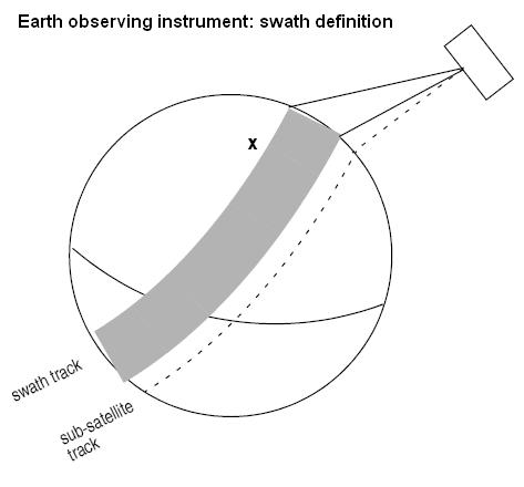
The term swath must be clearly defined to understand the explanations in this document:
  • instantaneous swath: the part of the earth surface observed by an instrument at a given time
  • swath track: represents the track made on the earth surface by the instantaneous swath over a period of time
For instruments observing the surface of the earth, the instantaneous swath is constituted by the point/curve/area on the ground observed by the instrument at a given time. It is calculated taking the earth ellipsoid as a reference for the earth surface. The wider the field-of-view of the instrument, the wider the swath on the ground.
When the satellite moves over a period of time, this point/curve/area defines a band on the earth surface. This constitutes the swath track.
See vollowing figure for an illustration of these definitions. Note that the terms curve or point are an idealized view of the instrument FOV, which usually have a thickness.
Earth-observing instrument: swath definition

Limb-sounding Instruments Swath Definition

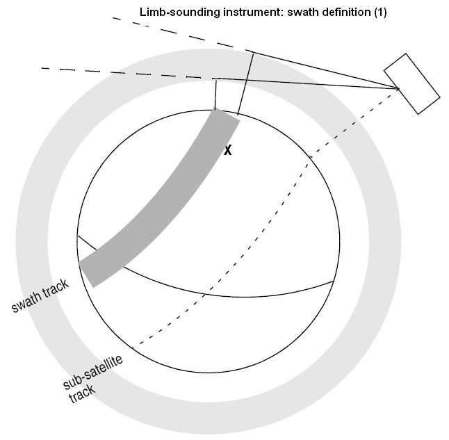
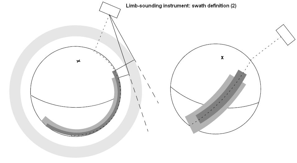
For limb sounding instruments, the concept can be generalized to define a "thick swath". This is obtained by defining a minimum and a maximum altitude, and considering the tangent points to these altitudes as the edges of the swath. Two cases have to be considered:
  • deterministic (narrow) azimuth field of view (e.g. MIPAS sideward-looking): the swath projection on the earth surface is similar to a regular sideward-looking swath, with the lower altitude defining the further swath edge and the higher altitude defining the closer swath edge. See following figure:
    Limb sounding instrument: swath definition (1)
  • non-deterministic (potentially wide) azimuth field of view (e.g. MIPAS rearward-looking): due to the potentially wide azimuth field of view, each altitude defines a swath projection on the earth surface. Depending on the altitude, these swaths are of different width across-track, and also at different distance from the satellite. See following figure:
    Limb sounding instrument: swath definition (2)
For these, 2 Instrument Swath Files are provided:
  • one at the highest altitude
  • one at the lowest altitude
The user must handle both swath himself to determine his required visibility time segments.

Limb-sounding Instruments Inertial Swath Definition

This type corresponds to the observation of inertial targets (e.g. Gomos occultation mode and Mipas Line of Sight mode in Envisat). For the CFI class method SwathStar::starVisTime the FOV direction in inertial coordinates must be available. Therefore for these instrument modes the direction in inertial space, for a given tangent altitude, is given in the swath template file.

Swath Definition for Envisat

Following table lists all instrument modes and the relevance of the swaths for Envisat-1. It shows also:
  • the prefix to be used when generating the swath template file name
  • the different types of algorithms to be used by Swath::genSwath (this is transparent to the user)
Instrument Mode File Prefix = swath Swath geometry (table 59) Swath Type Remarks
RA - RA_2__ POINTING (1 point) Nadir point Modeled as sub-satellite track
MERIS Averaging / Direct & Averaging MERIS_ POINTING (3 points) Nadir line -
ASAR Image Modes (IS1... IS7) SARxIM (x=1...7) ASAR Nadir line -
Alt. Polarization (IS1... IS7)
Wide Swath SARWIM
Global Monitoring
Wave (IS1... IS7) SARxWV (x=1...7) Modeled as a continuous swath anywhere within the image swath
GOMOS Occultation GOMOIL
GOMOIH
INERTIAL Inertial direction IFOV much smaller than swath. IFOV Very dependent on star availability.
2 swaths defined:
  • 1 for high altitude (GOMOIH)
  • 1 for low altitude (GOMOIL)
Occultation GOMO_H
GOMO_L
LIMB Limb wide Same mode as above, now swath defined as Earth-fixed location. IFOV much smaller than swath. IFOV Very dependent on star availability.
2 swaths defined:
  • 1 for high altitude (GOMO_H)
  • 1 for low altitude (GOMO_L)
SCIAMACHY Nadir / Nadir of Nadir & Limb SCIAN_ POINTING (3 points) Nadir line Continuous Nadir swath modeled
Limb / Limb of Nadir & Limb SCIALH
SCIALL
- Limb wide Same mode as above, now swath defined as Earth-fixed location. IFOV much smaller than swath. IFOV Very dependent on star availability.
2 swaths defined:
  • 1 for high altitude (SCIALH)
  • 1 for low altitude (SCIALL)
AATSR - ATSR_N
ATSR_F
POINTING (3 points) Nadir line 2 swaths defined:
  • 1 for nadir swath
  • 1 for forward swath
MWR - MWR___ POINTING (1 points) Nadir point Modeled as sub-satellite track
MIPAS Nominal MIPN_H
MIPN_L
LIMB Limb narrow 2 swaths defined:
    1 for high altitude (MIPN_H)
    1 for low altitude (MIPN_L)
Special Event Mode (across) MIP_X_ LIMB Limb narrow Modeled as an across track swath, in the middle of the MIPAS SEM acquisition scan.
Special Event Mode (rearward) MIP_RH
MIP_RL
LIMB Limb wide IFOV much smaller than swath. 2 swaths defined:
  • 1 for high altitude (MIP_RH)
  • 1 for low altitude (MIP_RL)
Rearward MIPIRH
MIPIRL
INERTIAL Inertial direction 2 swaths defined for rearward mode:
  • 1 for high altitude (MIPIRH)
  • 1 for low altitude (MIPIRL)
Sideward MIPIXH
MIPIXL
3 swaths defined for sideward mode:
  • 1 for high altitude (MIPIXH)
  • 1 for back mode (MIPIXB)
  • 1 for forward mode (MIPIXF)

Zone Borders and Projection

When defining a polygon zone, the user is assumed to wish polygon sides as straight lines. But on the earth surface, a straight line is, at best, a confusing concept.
The only way to define unambiguously straight lines is to work in a 2-dimensional projection of the earth surface. There are many possible projections, each having advantages and drawbacks.
Swath::zoneVisTime can handle zone borders in 2 different projections:
  • rectangular projection, using longitude and latitude as the X and Y axis; this is appropriate to express zones where (some of) the edges follow constant latitude lines, and provide a reasonable approximation for straight lines at low-medium latitudes
  • azimuthal gnomonic projection, where great circles are always projected as straight lines; this is better for high latitudes, where the rectangular projection suffers from too much distortion and the singularity at the poles.
Swath::zoneVisTime allows the user to specify which projection he wants to work in, i.e. in which projection the polygon sides will be represented by Swath::zoneVisTime as straight lines. The user is assumed to be aware of how the polygon sides behave on the Earth surface.

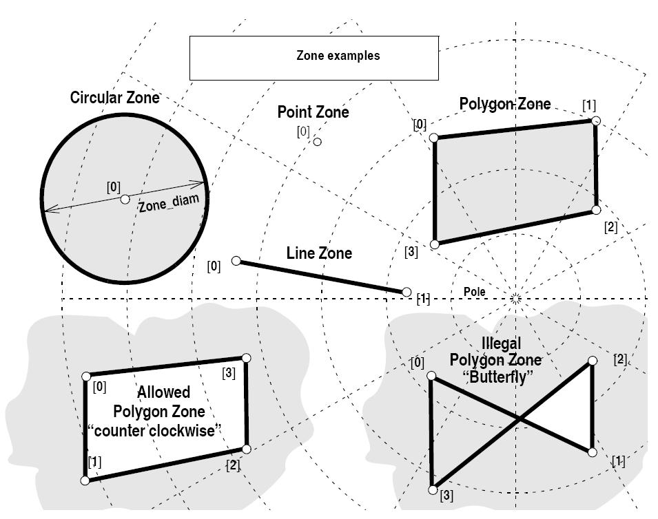
Zone Definition

The user-defined zone can be either:
  • a point
  • a line
  • a polygon
  • a circle
A zone is defined by the area of the earth surface enclosed by the zone borders:
  • in the case of a circular zone, the area inside the circle
  • in the case of a polygonal zone, the area which is always to the right of any polygon side; if the polygon is defined as a sequence of N points, each polygon side is considered as a line from point i to point i+1; this unambiguously defines the right side of the polygon sides.
Zone definition Zone_num Zone_long
Zone_lat
Zone_diam Description
Circular Zone 1 [0]: centre point yes
zone_diam > 0.0
The zone is represented as a circle, around the centre point
Point Zone 1 [0]: Point yes
zone_diam = 0.0
The zone is defined by the point. Resulting segments will have a zero duration. The zone will always be completely covered by the swath.
Line Zone 2 [0], [1]: Line no The zone is defined by the line from point [0] to point [1].
Polygon Zone >2 [i] no The zone is defined by the area right of the line from point [i] to point [i+1].

For the gnomonic projection, a side of a zone is always smaller than a half great circle, because two polygon points are considered to be joined by the shortest line.
For the rectangular projection, two consecutive points of the zone are also joined by the shortest line; so the difference in longitude must be less than 180 degrees.
The polygon zone can be closed (i.e. the first and last points are the same) or not. If the zone is not closed, Swath::zoneVisTime closes it by joining the last point with the first one in its internal computations.
See next figure for examples of zone definitions.
Swath::zoneVisTime will issue an error on the zone definition if the polygon has intersecting sides ("butterfly" zone)
Zone examples

Intersection Definition

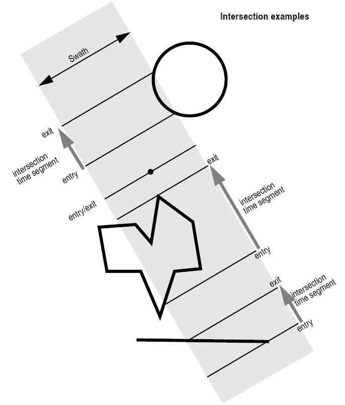
The Swath::zoneVisTime intersection times between the instrument swath and the user-defined zone are defined as the first and last occurrence, in chronological order with respect to the satellite direction, of the geometrical super-position of any point belonging to the instrument swath with any single point belonging to the zone (including the zone border).
The entry and exit times for each intersection are given as elapsed seconds (and microseconds) since the ascending node crossing.
Next figure shows some typical intersections:
Intersection examples

Intersection Algorithm

The intersection of a swath and a user-defined zone is to be performed on the Earth projected to a map plane in one of the following projections:
  • Rectangular projection
  • Gnomonic projection
Although the projections are quite different, the intersection rules are identical. The algorithm can however be different, in order to take advantage of a particular feature of a projection.
The purpose of the CFI function ZONEVISTIME is to obtain quickly, accurate intersection segments with a low precision (1 second).
The algorithms assume that the polygon zones are closed and expects a wrap around between the first and the last point. Thus ZONEVISTIME must first close the polygon if necessary. For ZONEVISTIME the following swath types are defined:
  • point swath: instantaneous swath is a point.
  • segment swath: instantaneous swath is a segment.
  • multi-segment swath: it can be open or closed.
  • inertial swath: not used by ZONEVISTIME
The main concept in the algorithm is the transition, defined as the change in coverage of (part of) the swath and the zone (e.g. edge of the swath crosses one polygon side).

Intersection with a point swath.

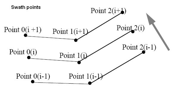
The vertices of the polygon defining the area are connected by straight lines in the chosen projection, along track swath points are also connected by straight lines in the same projection.
Transitions are located by linear intersection of the zone sides and the swath along track lines. A transition is only valid if the intersection occurs inside both line segments. The polygon side from <i> to <j> is defined in a clockwise manner inclusive point <i> but exclusive point <j>. The swath line from time <k> to <l> is defined inclusive the template point at <k> but exclusive the template point at <l>.
The fraction of the swath along track line determines the precise timing since time <k> of the intersection. Also the determination if the transition is a on- or off-transition is quite trivial. First a vector is defined, perpendicular to the along track swath line, such that the vector points left. Then, the dot product of the polygon side and this vector is calculated. If the dot product is positive, the transition is on, i.e. the swath enters the zone. If the result is negative, then the swath leaves the zone. If the result equals zero then the transition can be ignored (polygon side and swath overlay, a proper transition will be found with another pair of polygon side - swath line.).

Intersection with a segment swath

The left and right side of the swath, are located using the same algorithm as for the point swath. Even left and right time segments can be made based on the left and right hand transitions.
The polygon vertices (and not the sides) are intersected with the along track moving line swath, in order to catch zones smaller than the swath, etc. Swaths for intermediate times between two consecutive times in Swath Template File are considered straight segments, joining an intermediate point of the Left swath line from time <k> to time <l>, with an intermediate point in Right swath line.

Intersection with a multi-segment swath

The algorithm used for segment swath is repeated for every segment of the swath, and the visibility segments obtained in each case are merged with the ones of the other swath segments.
For a closed swath further calculations are done: it is checked if the zone is completely inside the swath area in the interval between contiguous visibility segments, or between the begining of the first orbit and the first visibility segment, or between the last visiblity segment and the end of the last orbit computed. If it is inside, segments must be merged because the zone was visible in the interval.
Swath points

Usage Hints

Limb-sounding Instruments Intersection

In the case of limb-sounding instrument with a potentially wide azimuth field of view, 2 swaths have to be considered (1 for minimum altitude, 1 for maximum altitude). Furthermore, these 2 swaths are offset in time (i.e. their projection on the earth intersect with a given point at different times). To cope with this, the user must do the following:
  • call Swath::zoneVisTime twice (once for each extreme altitude swath)
  • merge/filter the 2 sets of time segments, depending on what he wants to achieve

Zone Coverage

Swath::zoneVisTime computes purely geometrical intersections. The resulting zone visibility segments might need some additional filtering by the user. In particular, instrument constraints (e.g. only working outside of sun eclipse) have to be considered by the user.
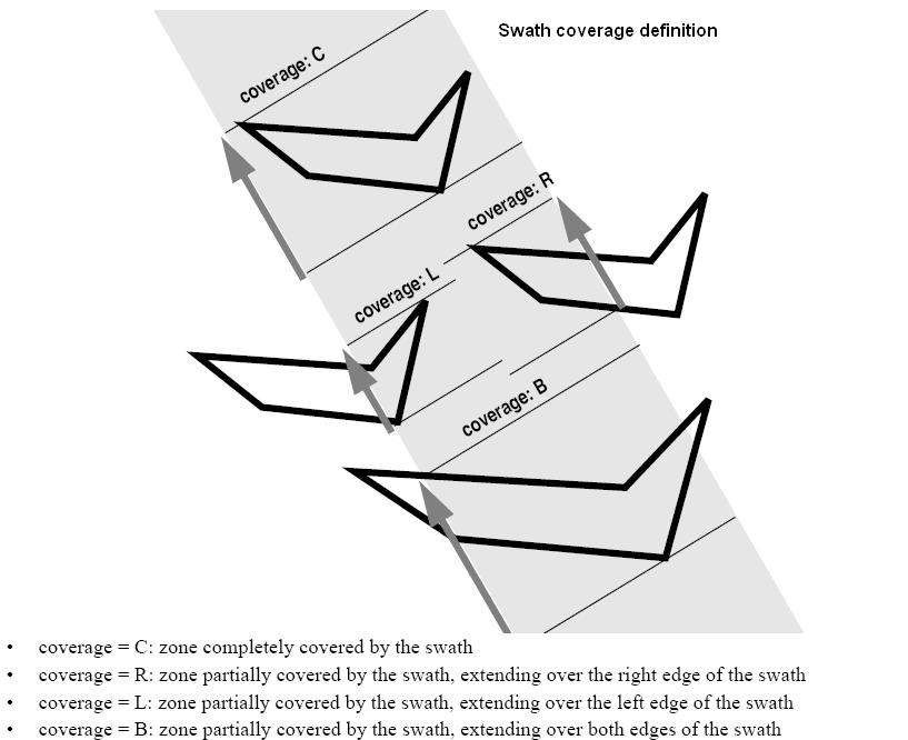
Furthermore, to help users to deal with zones wider than the swath (i.e. requiring several orbits to cover the whole zone), Swath::zoneVisTime produces for each zone visibility segment an indication of the coverage type (see next figure);
Swath coverage definition

Combined use of xv_swath_pos and the coverage flag

The EO_VISIBILITY function Swath::getPos can be used to refine the work performed with Swath::zoneVisTime.
Parameters:
startOrbit First absolute orbit, segment filter; segments will be filtered as from the beginning of first orbit. First Orbit for the orbit initialization will be used when absolute orbit is set to zero.
Allowed range: =0; or >=start_osf.
stopOrbit Last absolute orbit, segment filter. For orbitId initialized with orbital changes, when stopOrbit = 0 the stopOrbit will be set to the minimum value between:

  • the last orbit within the orbital change of the start_orbit.
  • startOrbit+cycle_length-1 (i.e. the input orbit range will be a complete cycle)

Allowed range: =0; or >=start_osf.

zoneId Identification of the zone, as defined in zoneDBFile.
zoneDBFile File name of the zone database file.
projection Projection used to define the polygon sides as straight lines (ProjectionEnum in VisibilityData.h).
minDuration Minimum duration for segments; only segments with a duration longer than minDuration will be given as output [s]. Allowed range: >=0.
Returns:
Visibility segments.
VisibilityList EECFI::Swath::zoneVisTime ( long  startOrbit,
long  stopOrbit,
long  projection,
const ZoneRec zoneRec,
double  minDuration 
) throw (CfiError)

Calculate zone visibility segments using a zone rec.

Parameters:
startOrbit First absolute orbit, segment filter; segments will be filtered as from the beginning of first orbit. First Orbit for the orbit initialization will be used when absolute orbit is set to zero.
Allowed range: =0; or >=start_osf.
stopOrbit Last absolute orbit, segment filter. For orbitId initialized with orbital changes, when stopOrbit = 0 the stopOrbit will be set to the minimum value between:

  • the last orbit within the orbital change of the start_orbit.
  • startOrbit+cycle_length-1 (i.e. the input orbit range will be a complete cycle)

Allowed range: =0; or >=start_osf.

projection Projection used to define the polygon sides as straight lines (ProjectionEnum in VisibilityData.h).
zoneRec Zone definition.
minDuration Minimum duration for segments; only segments with a duration longer than minDuration will be given as output [s]. Allowed range: >=0.
Returns:
Visibility segments.
VisibilityList EECFI::Swath::zoneVisTime ( long  startOrbit,
long  stopOrbit,
long  projection,
const StfFile stfFile,
const ZoneRec zoneRec,
double  minDuration 
) throw (CfiError)

Calculate zone visibility segments using a STF object and ZoneRec.

Parameters:
startOrbit First absolute orbit, segment filter; segments will be filtered as from the beginning of first orbit. First Orbit for the orbit initialization will be used when absolute orbit is set to zero.
Allowed range: =0; or >=start_osf.
stopOrbit Last absolute orbit, segment filter. For orbitId initialized with orbital changes, when stopOrbit = 0 the stopOrbit will be set to the minimum value between:

  • the last orbit within the orbital change of the start_orbit.
  • startOrbit+cycle_length-1 (i.e. the input orbit range will be a complete cycle)

Allowed range: =0; or >=start_osf.

stfFile Swath Template File object, it must have been read.
zoneRec Record with the zone information.
projection Projection used to define the polygon sides as straight lines (ProjectionEnum in VisibilityData.h).
zoneRec Zone definition.
minDuration Minimum duration for segments; only segments with a duration longer than minDuration will be given as output [s]. Allowed range: >=0.
Returns:
Visibility segments.

References EECFI::CfiError::addMsg().


Generated on Thu Jul 19 2012 15:37:08 for by doxygen 1.7.1