Earth Observation Mission CFI Software Visibility Software User Manual |
Earth Observation Mission CFI Software Visibility Software User Manual |
Class to make operations involving a swath for zone and station visibility. More...
Public Member Functions | |
| Swath () | |
| Default constructor. | |
| Swath (const OrbitId &orbitId, const std::string &swathFileName) | |
| Class constructor with parameters for STF file. | |
| Swath (const OrbitId &orbitId, long orbitNum, const std::string &swathFileName) | |
| Class constructor with parameters for SDF file. | |
| void | set (const OrbitId &orbitId, const std::string &swathFileName) |
| Set values of parameters with STF file. | |
| void | set (const OrbitId &orbitId, long orbitNum, const std::string &swathFileName) |
| Set values of parameterswith SDF file. | |
| void | set (const AtmosId &atmosId) |
| Set Atmosphere Id, necessary for swath generation. | |
| VisibilityList | zoneVisTime (long startOrbit, long stopOrbit, const std::string &zoneId, const std::string &zoneDBFile, long projection, double minDuration) const |
| Calculate zone visibility segments using a zone database. | |
| VisibilityList | zoneVisTime (long startOrbit, long stopOrbit, long projection, const ZoneRec &zoneRec, double minDuration) const |
| Calculate zone visibility segments using a zone rec. | |
| VisibilityList | zoneVisTime (long startOrbit, long stopOrbit, long projection, const StfFile &stfFile, const ZoneRec &zoneRec, double minDuration) const |
| Calculate zone visibility segments using a STF object and ZoneRec. | |
| VisibilityList | stationVisTime (long startOrbit, long stopOrbit, const std::string &staId, const std::string &staDBFile, long mask, double aosElevation, double losElevation, double minDuration) const |
| Calculate the visibility segments for which a satellite is visible from a ground station. | |
| VisibilityList | stationVisTime (long startOrbit, long stopOrbit, const StfFile &stfFile, const StationRec &staRec, long mask, double aosElevation, double losElevation, double minDuration) const |
| Calculate the visibility segments for which a satellite is visible from a ground station. | |
| VisibilityList | scVisTime (const SatNomTransId &satNomTransId1, const SatTransId &satTransId1, const InstrTransId &instrTransId1, long startOrbit, long stopOrbit, const OrbitId &orbitId2, const SatNomTransId &satNomTransId2, const SatTransId &satTransId2, const InstrTransId &instrTransId2, LinkData &linkData, double minDuration) const |
| void | setScVisTimeStep (double timeStep) |
| Update the time step used internally in the scVisTime function algorithm. | |
| VisibilityList | celestialBodyVisTime (const SatNomTransId &satNomTransId1, const SatTransId &satTransId1, const InstrTransId &instrTransId1, long startOrbit, long stopOrbit, long celestialBody_type, const LinkData &linkData, double minDuration) const |
| VisibilityList | multiZonesVisTime (long startOrbit, long stopOrbit, const std::vector< std::string > &zoneId, const std::string &zoneDBFile, const std::vector< long > &projection, const std::vector< ZoneRec > &zoneRec, double minDuration, bool extraInfoFlag) const |
| Calculates visibility segments for which the swath intersects a set of zones on the Earth ellipsoid. | |
| VisibilityList | multiStationsVisTime (long startOrbit, long stopOrbit, const std::vector< std::string > &staId, const std::string &staDBFile, const std::vector< double > &aosElevation, const std::vector< double > &losElevation, const std::vector< long > &mask, double minDuration, bool extraInfoFlag) const |
| Calculates visibility segments for which a satellite is visible from a set of ground stations. | |
| std::vector< VisibilityList > | mapping (long startOrbit, long stopOrbit, const std::string &zoneId, const std::string &zoneDBFile, long projection) const |
| Computes groups of visibility segments that cover the visiblity of a zone read from a database. | |
| std::vector< VisibilityList > | mapping (long startOrbit, long stopOrbit, long projection, const ZoneRec &zoneRec) const |
| Computes groups of visibility segments that cover the visiblity of a given zone. | |
| std::string | genSwath (long requestedOrbit, const std::string &dirName, const std::string &swathFile, const std::string &fileClass, long versionNumber, const std::string &fhSystem) const |
| Generate a swath template file using the SDF file. | |
| StfFile * | genSwath (long requestedOrbit, const SdfFile &sdfFile) const |
| Generate a STFFile object using the object SdfFile. | |
| std::vector< Geodetic > | getPos (const StfFile &stfFile, const ANXTime &anxTime) const |
| Gets the location of a swath at a given ANXTime. | |
| std::string | genScf (const std::string &instrument, const std::vector< TimelineInterval > &segments, const std::string &dirName, const std::string &scfFileName, const std::string &fileClass, long versionNumber, const std::string &fhSystem) const |
| Generate a swath control file. | |
| VisibilityList | zoneVisTimeCompute (AttitudeDef &attDef, SwathId &swathId, ZoneInfoList &zoneInfoList, VisTimeInterval &searchInterval) const |
| Compute zone visibility segments using input zone type. | |
| VisibilityList | stationVisTimeCompute (AttitudeDef &attDef, SwathId &swathId, StationInfoList &staInfoList, VisTimeInterval &searchInterval) const |
| Compute station visibility segments using input station type. | |
| std::vector< Geodetic > | getPosCompute (SwathId &swathId, VisTime &posTime) const |
| Gets the location of a swath at a given input time. | |
| std::vector< VisibilityList > | mappingCompute (SwathId &swathId, ZoneInfoList &zoneInfoList, VisTimeInterval &searchInterval) const |
| Computes groups of visibility segments that cover the visiblity of a zone read from a database. | |
Class to make operations involving a swath for zone and station visibility.
| EECFI::Swath::Swath | ( | ) |
Default constructor.
| EECFI::Swath::Swath | ( | const OrbitId & | orbitId, | |
| const std::string & | swathFileName | |||
| ) |
Class constructor with parameters for STF file.
| orbitId | Orbit Id. | |
| swathFileName | Swath template filename (path). |
| EECFI::Swath::Swath | ( | const OrbitId & | orbitId, | |
| long | orbitNum, | |||
| const std::string & | swathFileName | |||
| ) |
Class constructor with parameters for SDF file.
| orbitId | Orbit Id. | |
| orbitNum | Swath points are generated every "orbitNum" orbits. | |
| swathFileName | Swath definition filename (path). |
References EECFI::CfiError::addMsg().
| VisibilityList EECFI::Swath::celestialBodyVisTime | ( | const SatNomTransId & | satNomTransId1, | |
| const SatTransId & | satTransId1, | |||
| const InstrTransId & | instrTransId1, | |||
| long | startOrbit, | |||
| long | stopOrbit, | |||
| long | celestialBody_type, | |||
| const LinkData & | linkData, | |||
| double | minDuration | |||
| ) | const |
Calculates the visibility segments for which a Communication Terminal of a celestialBody object: moon/sun is visible from a FOV of a source satellite.
| satNomTransId1 | Satellite nominal attitude of source satellite. | |
| satTransId1 | Satellite attitude of source satellite. | |
| instrTransId1 | Instrument nominal attitude of source satellite. | |
| startOrbit | First absolute orbit, segment filter; segments will be filtered as from the beginning of first orbit. First Orbit for the orbit initialization will be used when absolute orbit is set to zero. Allowed range: =0; or >=start_osf. | |
| stopOrbit | Last absolute orbit, segment filter. For orbitId initialized with orbital changes, when stopOrbit = 0 the stopOrbit will be set to the minimum value between:
Allowed range: =0; or >=start_osf. | |
| celestialBody_type | Target celestial body (enumeration XVTypeCelestialBodyEnum). | |
| linkData | Link data between satellite and celestial body. Minimum tangent height and masks for visibility are configured. | |
| minDuration | Minimum duration for segments; only segments with a duration longer than minDuration will be given as output [s]. Allowed range: >=0. |
References EECFI::CfiError::addMsg(), EECFI::AzElMask::azimuth, EECFI::AzElMask::elevation, EECFI::LinkMask::exclMask, EECFI::LinkMask::inclMask, EECFI::LinkData::maskData, EECFI::ANXTime::microseconds, EECFI::LinkData::minTgHeight, EECFI::AzElMask::numMaskPt, EECFI::ANXTime::orbit, EECFI::ANXTime::seconds, EECFI::TimeSegment::start, EECFI::AzElMask::status, EECFI::CfiId::status(), EECFI::TimeSegment::stop, and EECFI::CfiClass::throwWarn.
| string EECFI::Swath::genScf | ( | const std::string & | instrument, | |
| const std::vector< TimelineInterval > & | segments, | |||
| const std::string & | dirName, | |||
| const std::string & | scfFileName, | |||
| const std::string & | fileClass, | |||
| long | versionNumber, | |||
| const std::string & | fhSystem | |||
| ) | const |
Generate a swath control file.
This file contains a list of visibility segments together with some features linked to the segment that are used for the visualisation of the segment in the ESOV tool.
| instrument | Instrument name. | |
| segments | vector of timelines intervals . | |
| dirName | Directory where resulting STF is written. | |
| scfFileName | Name for output swath file. If empty ("") the software will generate the name according to file name specifications. | |
| fileClass | File class for output file. | |
| versionNumber | Version number of output file. Allowed range: >=1. | |
| fhSystem | System field of the output fixed header. |
References EECFI::CfiError::addMsg(), EECFI::CfiId::status(), and EECFI::CfiClass::throwWarn.
| string EECFI::Swath::genSwath | ( | long | requestedOrbit, | |
| const std::string & | dirName, | |||
| const std::string & | swathFile, | |||
| const std::string & | fileClass, | |||
| long | versionNumber, | |||
| const std::string & | fhSystem | |||
| ) | const |
Generate a swath template file using the SDF file.
The atmospheric and refraction model is determined by the AtmosId object. If AtmosId is not set, refraction will not be considered
| Swath geometry definition (algorithm) Geometry |
Algorithm description | Swath point type |
|---|---|---|
| Pointing_Geometry (azimuth, elevation, altitude) | Swath point computed with Target::targetInter with that azimuth, elevation and altitude | Geodetic |
| Distance_Geometry (azimuth, elevation, altitude, distance) | Swath point computed with Target::targetGroundRange with that azimuth, elevation, altitude and distance | Geodetic |
| Limb_Geometry (azimuth and altitude) | Swath point computed with Target::targetAltitude with that azimuth and altitude | Geodetic |
| Inertial_Geometry (azimuth and altitude) | Swath point computed with Target::targetAltitude with that azimuth and altitude. The swath point is the RA and Declination of the target. | Inertial |
| Sub_Satellite_Geometry (no parameters) | Computation of the sub-satellite point | Geodetic |
| ASAR_Geometry (azimuth, elevation, altitude) | Specific algorithm for the three swath points for ASAR instrument in Envisat. | Geodetic |
| requestedOrbit | Absolute orbit for which the instrument swath template file will be calculated. | |
| dirName | Directory where the resulting STF is written (current directory used ir empty string). | |
| swathFile | Name for output swath file (if empty, the name will be generated according to file name specifications). | |
| fileClass | File class for output swath file. | |
| versionNumber | Version number for output swath file. Allowed range: >=1. | |
| fhSystem | System field of the output swath file fixed header. |
References EECFI::CfiError::addMsg(), EECFI::CfiId::status(), and EECFI::CfiClass::throwWarn.
Generate a STFFile object using the object SdfFile.
OrbitId must be set. The atmospheric and refraction model is determined by the AtmosId object. If AtmosId is not set, refraction will not be considered.
| requestedOrbit | Absolute orbit for which the instrument swath template file will be calculated. | |
| sdfFile | Swath Definition File object. It must have been read. |
References EECFI::CfiError::addMsg(), EECFI::SdfFile::sdfRec, EECFI::CfiId::status(), and EECFI::CfiClass::throwWarn.
Gets the location of a swath at a given ANXTime.
| stfFile | Object with Swath Template File read. | |
| anxTime | Absolute orbit and time where position wants to be calculated. |
References EECFI::CfiError::addMsg(), EECFI::Geodetic::alt, EECFI::Geodetic::altDer, EECFI::Geodetic::deriv, EECFI::Geodetic::lat, EECFI::Geodetic::latDer, EECFI::Geodetic::lon, EECFI::Geodetic::lonDer, EECFI::ANXTime::microseconds, EECFI::ANXTime::orbit, EECFI::ANXTime::seconds, EECFI::CfiId::status(), and EECFI::CfiClass::throwWarn.
Gets the location of a swath at a given input time.
| swathId | Swath Id. | |
| posTime | Time/orbit requested. |
References EECFI::CfiError::addMsg(), EECFI::Geodetic::alt, EECFI::Geodetic::altDer, EECFI::Geodetic::deriv, EECFI::Geodetic::lat, EECFI::Geodetic::latDer, EECFI::Geodetic::lon, EECFI::Geodetic::lonDer, EECFI::VisTime::msec, EECFI::VisTime::orbitNum, EECFI::VisTime::sec, EECFI::CfiId::status(), EECFI::CfiClass::throwWarn, EECFI::VisTime::type, and EECFI::VisTime::utcTime.
| vector< VisibilityList > EECFI::Swath::mapping | ( | long | startOrbit, | |
| long | stopOrbit, | |||
| const std::string & | zoneId, | |||
| const std::string & | zoneDBFile, | |||
| long | projection | |||
| ) | const |
Computes groups of visibility segments that cover the visiblity of a zone read from a database.
| startOrbit | First absolute orbit, segment filter; segments will be filtered as from the beginning of first orbit. First Orbit for the orbit initialization will be used when absolute orbit is set to zero. Allowed range: =0; or >=start_osf. | |
| stopOrbit | Last absolute orbit, segment filter. For orbitId initialized with orbital changes, when stopOrbit = 0 the stopOrbit will be set to the minimum value between:
Allowed range: =0; or >=start_osf. | |
| zoneId | Identification of the zone, as defined in zoneDBFile. | |
| zoneDBFile | File name of the zone database file. | |
| projection | Projection used to define the polygon sides as straight lines (ProjectionEnum in VisibilityData.h). |
Referenced by mapping().
| vector< VisibilityList > EECFI::Swath::mapping | ( | long | startOrbit, | |
| long | stopOrbit, | |||
| long | projection, | |||
| const ZoneRec & | zoneRec | |||
| ) | const |
Computes groups of visibility segments that cover the visiblity of a given zone.
| startOrbit | First absolute orbit, segment filter; segments will be filtered as from the beginning of first orbit. First Orbit for the orbit initialization will be used when absolute orbit is set to zero. Allowed range: =0; or >=start_osf. | |
| stopOrbit | Last absolute orbit, segment filter. For orbitId initialized with orbital changes, when stopOrbit = 0 the stopOrbit will be set to the minimum value between:
Allowed range: =0; or >=start_osf. | |
| projection | Projection used to define the polygon sides as straight lines (ProjectionEnum in VisibilityData.h). | |
| zoneRec | Zone definition. |
References mapping().
| vector< VisibilityList > EECFI::Swath::mappingCompute | ( | SwathId & | swathId, | |
| ZoneInfoList & | zoneInfoList, | |||
| VisTimeInterval & | searchInterval | |||
| ) | const |
Computes groups of visibility segments that cover the visiblity of a zone read from a database.
References EECFI::CfiError::addMsg(), EECFI::ZoneInfoList::calcFlag, EECFI::VisTime::msec, EECFI::VisTime::orbitNum, EECFI::VisTime::sec, EECFI::CfiId::status(), EECFI::CfiClass::throwWarn, EECFI::VisTimeInterval::tstart, EECFI::VisTimeInterval::tstop, EECFI::VisTime::type, EECFI::VisTime::utcTime, and EECFI::ZoneInfoList::zoneInfo.
| VisibilityList EECFI::Swath::multiStationsVisTime | ( | long | startOrbit, | |
| long | stopOrbit, | |||
| const std::vector< std::string > & | staId, | |||
| const std::string & | staDBFile, | |||
| const std::vector< double > & | aosElevation, | |||
| const std::vector< double > & | losElevation, | |||
| const std::vector< long > & | mask, | |||
| double | minDuration, | |||
| bool | extraInfoFlag | |||
| ) | const |
Calculates visibility segments for which a satellite is visible from a set of ground stations.
| startOrbit | First absolute orbit, segment filter; segments will be filtered as from the beginning of first orbit. First Orbit for the orbit initialization will be used when absolute orbit is set to zero. Allowed range: =0; or >=start_osf. | |
| stopOrbit | Last absolute orbit, segment filter. For orbitId initialized with orbital changes, when stopOrbit = 0 the stopOrbit will be set to the minimum value between:
Allowed range: =0; or >=start_osf. | |
| staId | Identification of the stations, as defined in staDBFile. | |
| staDBFile | File name of the station database file. | |
| mask | Mask used to define visibility (MaskEnum in VisibilityData.h). | |
| aosElevation | Minimum elevation to consider at AOS [deg]. Allowed range: >=0.0. | |
| losElevation | Maximum elevation to consider at LOS [deg]. Allowed range: >=0.0 ; <=aosElevation. | |
| minDuration | Minimum duration for segments; only segments with a duration longer than minDuration will be given as output [s]. Allowed range: >=0. | |
| extraInfoFlag | If true, numberOfStations and stationsInSegment are calculated (see VisibilitySegment.h). |
References EECFI::CfiError::addMsg(), EECFI::CfiId::status(), and EECFI::CfiClass::throwWarn.
| VisibilityList EECFI::Swath::multiZonesVisTime | ( | long | startOrbit, | |
| long | stopOrbit, | |||
| const std::vector< std::string > & | zoneId, | |||
| const std::string & | zoneDBFile, | |||
| const std::vector< long > & | projection, | |||
| const std::vector< ZoneRec > & | zoneRec, | |||
| double | minDuration, | |||
| bool | extraInfoFlag | |||
| ) | const |
Calculates visibility segments for which the swath intersects a set of zones on the Earth ellipsoid.
| startOrbit | First absolute orbit, segment filter; segments will be filtered as from the beginning of first orbit. First Orbit for the orbit initialization will be used when absolute orbit is set to zero. Allowed range: =0; or >=start_osf. | |
| stopOrbit | Last absolute orbit, segment filter. For orbitId initialized with orbital changes, when stopOrbit = 0 the stopOrbit will be set to the minimum value between:
Allowed range: =0; or >=start_osf. | |
| zoneId | Identification of the zones (it must be one for every zone, not only the ones read from database, but the stations read from database must be placed first in vector). | |
| zoneDBFile | File name of the zone database file. | |
| projection | Projection used to define the polygon sides as straight lines (ProjectionEnum in VisibilityData.h). | |
| zoneRec | Zones definition. | |
| minDuration | Minimum duration for segments; only segments with a duration longer than minDuration will be given as output [s]. Allowed range: >=0. | |
| extraInfoFlag | If true, numberOfZones, zonesInSegment and multiCoverage are calculated (see VisibilitySegment.h). |
References EECFI::CfiError::addMsg(), EECFI::CfiId::status(), and EECFI::CfiClass::throwWarn.
| VisibilityList EECFI::Swath::scVisTime | ( | const SatNomTransId & | satNomTransId1, | |
| const SatTransId & | satTransId1, | |||
| const InstrTransId & | instrTransId1, | |||
| long | startOrbit, | |||
| long | stopOrbit, | |||
| const OrbitId & | orbitId2, | |||
| const SatNomTransId & | satNomTransId2, | |||
| const SatTransId & | satTransId2, | |||
| const InstrTransId & | instrTransId2, | |||
| LinkData & | linkData, | |||
| double | minDuration | |||
| ) | const |
Calculates the visibility segments for which a Communication Terminal of a target satellite is visible from a Communication Terminal of a source satellite.
| satNomTransId1 | Satellite nominal attitude of source satellite. | |
| satTransId1 | Satellite attitude of source satellite. | |
| instrTransId1 | Instrument nominal attitude of source satellite. | |
| startOrbit | First absolute orbit, segment filter; segments will be filtered as from the beginning of first orbit. First Orbit for the orbit initialization will be used when absolute orbit is set to zero. Allowed range: =0; or >=start_osf. | |
| stopOrbit | Last absolute orbit, segment filter. For orbitId initialized with orbital changes, when stopOrbit = 0 the stopOrbit will be set to the minimum value between:
Allowed range: =0; or >=start_osf. | |
| satNomTransId2 | Satellite nominal attitude of target satellite. | |
| satTransId2 | Satellite attitude of target satellite. | |
| instrTransId2 | Instrument nominal attitude of target satellite. | |
| linkData | Link data between both satellites. Minimum tangent height and masks for visibility are configured. | |
| minDuration | Minimum duration for segments; only segments with a duration longer than minDuration will be given as output [s]. Allowed range: >=0. |
References EECFI::CfiError::addMsg(), EECFI::ANXTime::microseconds, EECFI::ANXTime::orbit, EECFI::ANXTime::seconds, EECFI::TimeSegment::start, EECFI::CfiError::status(), and EECFI::TimeSegment::stop.
| void EECFI::Swath::set | ( | const OrbitId & | orbitId, | |
| long | orbitNum, | |||
| const std::string & | swathFileName | |||
| ) |
Set values of parameterswith SDF file.
| orbitId | Orbit Id. | |
| orbitNum | Swath points are generated every "orbitNum" orbits. | |
| swathFileName | Swath definition filename (path). |
References EECFI::CfiError::addMsg().
| void EECFI::Swath::set | ( | const OrbitId & | orbitId, | |
| const std::string & | swathFileName | |||
| ) |
Set values of parameters with STF file.
| orbitId | Orbit Id. | |
| swathFileName | Swath template filename (path). |
| void EECFI::Swath::set | ( | const AtmosId & | atmosId | ) |
| void EECFI::Swath::setScVisTimeStep | ( | double | timeStep | ) |
Update the time step used internally in the scVisTime function algorithm.
| timeStep | Time step to be used internally in scVisTime algorithm [seconds]. |
References EECFI::CfiError::addMsg(), EECFI::CfiId::status(), and EECFI::CfiClass::throwWarn.
| VisibilityList EECFI::Swath::stationVisTime | ( | long | startOrbit, | |
| long | stopOrbit, | |||
| const StfFile & | stfFile, | |||
| const StationRec & | staRec, | |||
| long | mask, | |||
| double | aosElevation, | |||
| double | losElevation, | |||
| double | minDuration | |||
| ) | const |
Calculate the visibility segments for which a satellite is visible from a ground station.
| startOrbit | First absolute orbit, segment filter; segments will be filtered as from the beginning of first orbit. First Orbit for the orbit initialization will be used when absolute orbit is set to zero. Allowed range: =0; or >=start_osf. | |
| stopOrbit | Last absolute orbit, segment filter. For orbitId initialized with orbital changes, when stopOrbit = 0 the stopOrbit will be set to the minimum value between:
Allowed range: =0; or >=start_osf. | |
| stfFile | StfFile object with STF information. File must have been read. | |
| staRec | Station data. | |
| mask | Mask used to define visibility (MaskEnum in VisibilityData.h). | |
| aosElevation | Minimum elevation to consider at AOS [deg]. Allowed range: >=0.0. | |
| losElevation | Maximum elevation to consider at LOS [deg]. Allowed range: >=0.0 ; <=aosElevation. | |
| minDuration | Minimum duration for segments; only segments with a duration longer than minDuration will be given as output [s]. Allowed range: >=0. |
References EECFI::CfiError::addMsg(), EECFI::StationRec::antenna, EECFI::StationRec::azimuth, EECFI::StationRec::descriptor, EECFI::StationRec::elevation, EECFI::StationRec::latMax, EECFI::StationRec::latMin, EECFI::StationRec::longMax, EECFI::StationRec::longMin, EECFI::ANXTime::microseconds, EECFI::StationRec::missionAosEl, EECFI::StationRec::missionList, EECFI::StationRec::missionLosEl, EECFI::StationRec::missionMaskType, EECFI::StationRec::missionName, EECFI::StationRec::numMaskPt, EECFI::ANXTime::orbit, EECFI::StationRec::points, EECFI::StationRec::projLat, EECFI::StationRec::projLong, EECFI::StationRec::purpose, EECFI::ANXTime::seconds, EECFI::TimeSegment::start, EECFI::StationRec::stationAlt, EECFI::StationRec::stationId, EECFI::StationRec::stationLat, EECFI::StationRec::stationLong, EECFI::CfiId::status(), EECFI::TimeSegment::stop, EECFI::CfiClass::throwWarn, and EECFI::StationRec::type.
| VisibilityList EECFI::Swath::stationVisTime | ( | long | startOrbit, | |
| long | stopOrbit, | |||
| const std::string & | staId, | |||
| const std::string & | staDBFile, | |||
| long | mask, | |||
| double | aosElevation, | |||
| double | losElevation, | |||
| double | minDuration | |||
| ) | const |
Calculate the visibility segments for which a satellite is visible from a ground station.
| startOrbit | First absolute orbit, segment filter; segments will be filtered as from the beginning of first orbit. First Orbit for the orbit initialization will be used when absolute orbit is set to zero. Allowed range: =0; or >=start_osf. | |
| stopOrbit | Last absolute orbit, segment filter. For orbitId initialized with orbital changes, when stopOrbit = 0 the stopOrbit will be set to the minimum value between:
Allowed range: =0; or >=start_osf. | |
| staId | Identification of the station, as defined in staDBFile. | |
| staDBFile | File name of the station database file. | |
| mask | Mask used to define visibility (MaskEnum in VisibilityData.h). | |
| aosElevation | Minimum elevation to consider at AOS [deg]. Allowed range: >=0.0. | |
| losElevation | Maximum elevation to consider at LOS [deg]. Allowed range: >=0.0 ; <=aosElevation. | |
| minDuration | Minimum duration for segments; only segments with a duration longer than minDuration will be given as output [s]. Allowed range: >=0. |
References EECFI::CfiError::addMsg(), EECFI::ANXTime::microseconds, EECFI::ANXTime::orbit, EECFI::ANXTime::seconds, EECFI::TimeSegment::start, EECFI::CfiId::status(), EECFI::TimeSegment::stop, and EECFI::CfiClass::throwWarn.
| VisibilityList EECFI::Swath::stationVisTimeCompute | ( | AttitudeDef & | attDef, | |
| SwathId & | swathId, | |||
| StationInfoList & | staInfoList, | |||
| VisTimeInterval & | searchInterval | |||
| ) | const |
Compute station visibility segments using input station type.
| attDef | Attitude definition to be used. | |
| swathId | Swath ID with swath data for internal computations. | |
| staInfoList | List of stations. | |
| searchInterval | Interval to be used for visibility computations. |
References EECFI::CfiError::addMsg(), EECFI::StationInfoList::calcFlag, EECFI::AttitudeDef::instrTransId, EECFI::ANXTime::microseconds, EECFI::VisTime::msec, EECFI::ANXTime::orbit, EECFI::VisTime::orbitNum, EECFI::AttitudeDef::satNomTransId, EECFI::AttitudeDef::satTransId, EECFI::VisTime::sec, EECFI::ANXTime::seconds, EECFI::TimeSegment::start, EECFI::StationInfoList::stationInfo, EECFI::CfiId::status(), EECFI::TimeSegment::stop, EECFI::CfiClass::throwWarn, EECFI::VisTimeInterval::tstart, EECFI::VisTimeInterval::tstop, EECFI::VisibilitySegment::type, EECFI::AttitudeDef::type, EECFI::VisTime::type, EECFI::VisTime::utcTime, EECFI::VisibilitySegment::utcTimeStart, and EECFI::VisibilitySegment::utcTimeStop.
| VisibilityList EECFI::Swath::zoneVisTime | ( | long | startOrbit, | |
| long | stopOrbit, | |||
| long | projection, | |||
| const ZoneRec & | zoneRec, | |||
| double | minDuration | |||
| ) | const |
Calculate zone visibility segments using a zone rec.
| startOrbit | First absolute orbit, segment filter; segments will be filtered as from the beginning of first orbit. First Orbit for the orbit initialization will be used when absolute orbit is set to zero. Allowed range: =0; or >=start_osf. | |
| stopOrbit | Last absolute orbit, segment filter. For orbitId initialized with orbital changes, when stopOrbit = 0 the stopOrbit will be set to the minimum value between:
Allowed range: =0; or >=start_osf. | |
| projection | Projection used to define the polygon sides as straight lines (ProjectionEnum in VisibilityData.h). | |
| zoneRec | Zone definition. | |
| minDuration | Minimum duration for segments; only segments with a duration longer than minDuration will be given as output [s]. Allowed range: >=0. |
References zoneVisTime().
| VisibilityList EECFI::Swath::zoneVisTime | ( | long | startOrbit, | |
| long | stopOrbit, | |||
| long | projection, | |||
| const StfFile & | stfFile, | |||
| const ZoneRec & | zoneRec, | |||
| double | minDuration | |||
| ) | const |
Calculate zone visibility segments using a STF object and ZoneRec.
| startOrbit | First absolute orbit, segment filter; segments will be filtered as from the beginning of first orbit. First Orbit for the orbit initialization will be used when absolute orbit is set to zero. Allowed range: =0; or >=start_osf. | |
| stopOrbit | Last absolute orbit, segment filter. For orbitId initialized with orbital changes, when stopOrbit = 0 the stopOrbit will be set to the minimum value between:
Allowed range: =0; or >=start_osf. | |
| stfFile | Swath Template File object, it must have been read. | |
| zoneRec | Record with the zone information. | |
| projection | Projection used to define the polygon sides as straight lines (ProjectionEnum in VisibilityData.h). | |
| zoneRec | Zone definition. | |
| minDuration | Minimum duration for segments; only segments with a duration longer than minDuration will be given as output [s]. Allowed range: >=0. |
References EECFI::CfiError::addMsg(), EECFI::ZoneRec::creator, EECFI::ZoneRec::description, EECFI::ZoneRec::projection, EECFI::CfiId::status(), EECFI::ZoneRec::surface, EECFI::CfiClass::throwWarn, EECFI::ZoneRec::zoneDiam, EECFI::ZoneRec::zoneId, EECFI::ZoneRec::zonePoint, and EECFI::ZoneRec::zoneType.
| VisibilityList EECFI::Swath::zoneVisTime | ( | long | startOrbit, | |
| long | stopOrbit, | |||
| const std::string & | zoneId, | |||
| const std::string & | zoneDBFile, | |||
| long | projection, | |||
| double | minDuration | |||
| ) | const |
Calculate zone visibility segments using a zone database.
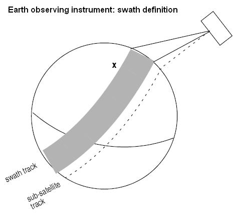
| Instrument | Mode | File Prefix = swath | Swath geometry (table 59) | Swath Type | Remarks |
|---|---|---|---|---|---|
| RA | - | RA_2__ | POINTING (1 point) | Nadir point | Modeled as sub-satellite track |
| MERIS | Averaging / Direct & Averaging | MERIS_ | POINTING (3 points) | Nadir line | - |
| ASAR | Image Modes (IS1... IS7) | SARxIM (x=1...7) | ASAR | Nadir line | - |
| Alt. Polarization (IS1... IS7) | |||||
| Wide Swath | SARWIM | ||||
| Global Monitoring | |||||
| Wave (IS1... IS7) | SARxWV (x=1...7) | Modeled as a continuous swath anywhere within the image swath | |||
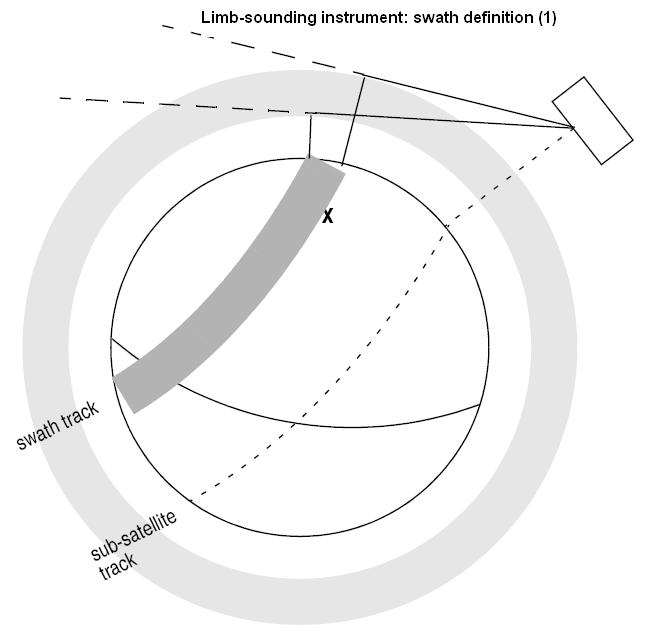
| GOMOS | Occultation | GOMOIL GOMOIH |
INERTIAL | Inertial direction | IFOV much smaller than swath. IFOV Very dependent on star availability. 2 swaths defined:
|
| Occultation | GOMO_H GOMO_L |
LIMB | Limb wide | Same mode as above, now swath defined as Earth-fixed location.
IFOV much smaller than swath. IFOV Very dependent on star availability. 2 swaths defined:
|
|
| SCIAMACHY | Nadir / Nadir of Nadir & Limb | SCIAN_ | POINTING (3 points) | Nadir line | Continuous Nadir swath modeled |
| Limb / Limb of Nadir & Limb | SCIALH SCIALL |
- | Limb wide | Same mode as above, now swath defined as Earth-fixed location.
IFOV much smaller than swath. IFOV Very dependent on star availability. 2 swaths defined:
|
|
| AATSR | - | ATSR_N ATSR_F |
POINTING (3 points) | Nadir line | 2 swaths defined:
|
| MWR | - | MWR___ | POINTING (1 points) | Nadir point | Modeled as sub-satellite track |
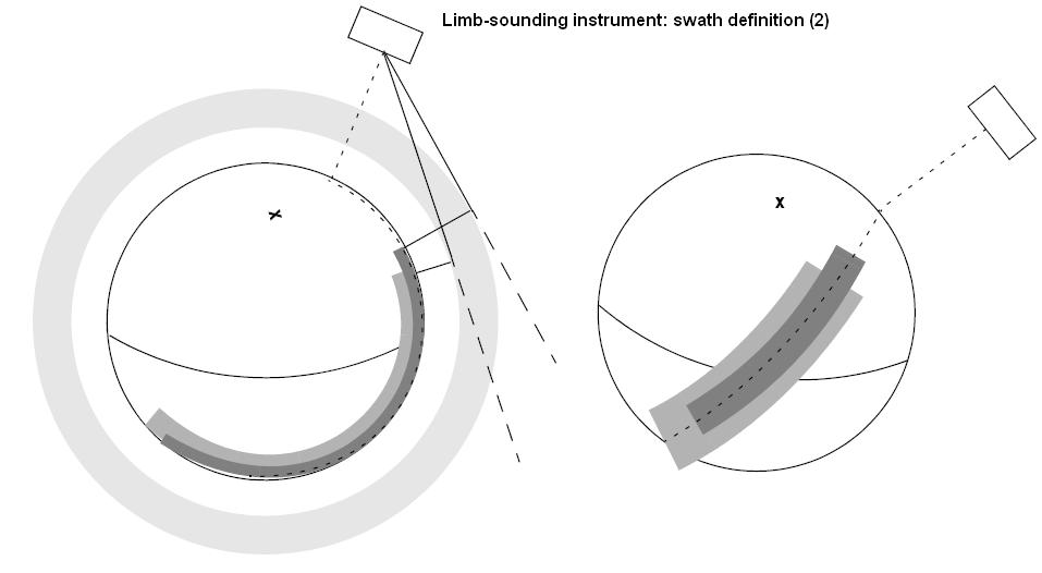
| MIPAS | Nominal | MIPN_H MIPN_L |
LIMB | Limb narrow | 2 swaths defined:
|
| Special Event Mode (across) | MIP_X_ | LIMB | Limb narrow | Modeled as an across track swath, in the middle of the MIPAS SEM acquisition scan. | |
| Special Event Mode (rearward) | MIP_RH MIP_RL |
LIMB | Limb wide | IFOV much smaller than swath.
2 swaths defined:
|
|
| Rearward | MIPIRH MIPIRL |
INERTIAL | Inertial direction | 2 swaths defined for rearward mode:
|
|
| Sideward | MIPIXH MIPIXL |
3 swaths defined for sideward mode:
|
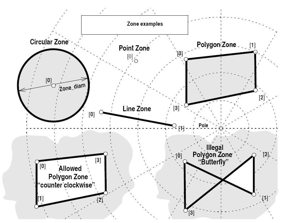
| Zone definition | Zone_num | Zone_long Zone_lat |
Zone_diam | Description |
|---|---|---|---|---|
| Circular Zone | 1 | [0]: centre point | yes zone_diam > 0.0 |
The zone is represented as a circle, around the centre point |
| Point Zone | 1 | [0]: Point | yes zone_diam = 0.0 |
The zone is defined by the point. Resulting segments will have a zero duration. The zone will always be completely covered by the swath. |
| Line Zone | 2 | [0], [1]: Line | no | The zone is defined by the line from point [0] to point [1]. |
| Polygon Zone | >2 | [i] | no | The zone is defined by the area right of the line from point [i] to point [i+1]. |
| startOrbit | First absolute orbit, segment filter; segments will be filtered as from the beginning of first orbit. First Orbit for the orbit initialization will be used when absolute orbit is set to zero. Allowed range: =0; or >=start_osf. | |
| stopOrbit | Last absolute orbit, segment filter. For orbitId initialized with orbital changes, when stopOrbit = 0 the stopOrbit will be set to the minimum value between:
Allowed range: =0; or >=start_osf. | |
| zoneId | Identification of the zone, as defined in zoneDBFile. | |
| zoneDBFile | File name of the zone database file. | |
| projection | Projection used to define the polygon sides as straight lines (ProjectionEnum in VisibilityData.h). | |
| minDuration | Minimum duration for segments; only segments with a duration longer than minDuration will be given as output [s]. Allowed range: >=0. |
Referenced by zoneVisTime().
| VisibilityList EECFI::Swath::zoneVisTimeCompute | ( | AttitudeDef & | attDef, | |
| SwathId & | swathId, | |||
| ZoneInfoList & | zoneInfoList, | |||
| VisTimeInterval & | searchInterval | |||
| ) | const |
Compute zone visibility segments using input zone type.
| Instrument | Mode | File Prefix = swath | Swath geometry (table 59) | Swath Type | Remarks |
|---|---|---|---|---|---|
| RA | - | RA_2__ | POINTING (1 point) | Nadir point | Modeled as sub-satellite track |
| MERIS | Averaging / Direct & Averaging | MERIS_ | POINTING (3 points) | Nadir line | - |
| ASAR | Image Modes (IS1... IS7) | SARxIM (x=1...7) | ASAR | Nadir line | - |
| Alt. Polarization (IS1... IS7) | |||||
| Wide Swath | SARWIM | ||||
| Global Monitoring | |||||
| Wave (IS1... IS7) | SARxWV (x=1...7) | Modeled as a continuous swath anywhere within the image swath | |||
| GOMOS | Occultation | GOMOIL GOMOIH |
INERTIAL | Inertial direction | IFOV much smaller than swath. IFOV Very dependent on star availability. 2 swaths defined:
|
| Occultation | GOMO_H GOMO_L |
LIMB | Limb wide | Same mode as above, now swath defined as Earth-fixed location.
IFOV much smaller than swath. IFOV Very dependent on star availability. 2 swaths defined:
|
|
| SCIAMACHY | Nadir / Nadir of Nadir & Limb | SCIAN_ | POINTING (3 points) | Nadir line | Continuous Nadir swath modeled |
| Limb / Limb of Nadir & Limb | SCIALH SCIALL |
- | Limb wide | Same mode as above, now swath defined as Earth-fixed location.
IFOV much smaller than swath. IFOV Very dependent on star availability. 2 swaths defined:
|
|
| AATSR | - | ATSR_N ATSR_F |
POINTING (3 points) | Nadir line | 2 swaths defined:
|
| MWR | - | MWR___ | POINTING (1 points) | Nadir point | Modeled as sub-satellite track |
| MIPAS | Nominal | MIPN_H MIPN_L |
LIMB | Limb narrow | 2 swaths defined:
|
| Special Event Mode (across) | MIP_X_ | LIMB | Limb narrow | Modeled as an across track swath, in the middle of the MIPAS SEM acquisition scan. | |
| Special Event Mode (rearward) | MIP_RH MIP_RL |
LIMB | Limb wide | IFOV much smaller than swath.
2 swaths defined:
|
|
| Rearward | MIPIRH MIPIRL |
INERTIAL | Inertial direction | 2 swaths defined for rearward mode:
|
|
| Sideward | MIPIXH MIPIXL |
3 swaths defined for sideward mode:
|
| Zone definition | Zone_num | Zone_long Zone_lat |
Zone_diam | Description |
|---|---|---|---|---|
| Circular Zone | 1 | [0]: centre point | yes zone_diam > 0.0 |
The zone is represented as a circle, around the centre point |
| Point Zone | 1 | [0]: Point | yes zone_diam = 0.0 |
The zone is defined by the point. Resulting segments will have a zero duration. The zone will always be completely covered by the swath. |
| Line Zone | 2 | [0], [1]: Line | no | The zone is defined by the line from point [0] to point [1]. |
| Polygon Zone | >2 | [i] | no | The zone is defined by the area right of the line from point [i] to point [i+1]. |
| attDef | Definition of attitudes.. | |
| swathId | Swath Id. | |
| zoneInfoList | Zone(s) information. |
References EECFI::CfiError::addMsg(), EECFI::ZoneInfoList::calcFlag, EECFI::AttitudeDef::instrTransId, EECFI::ANXTime::microseconds, EECFI::VisTime::msec, EECFI::ANXTime::orbit, EECFI::VisTime::orbitNum, EECFI::AttitudeDef::satNomTransId, EECFI::AttitudeDef::satTransId, EECFI::VisTime::sec, EECFI::ANXTime::seconds, EECFI::TimeSegment::start, EECFI::CfiId::status(), EECFI::TimeSegment::stop, EECFI::CfiClass::throwWarn, EECFI::VisTimeInterval::tstart, EECFI::VisTimeInterval::tstop, EECFI::VisibilitySegment::type, EECFI::AttitudeDef::type, EECFI::VisTime::type, EECFI::VisTime::utcTime, EECFI::VisibilitySegment::utcTimeStart, EECFI::VisibilitySegment::utcTimeStop, and EECFI::ZoneInfoList::zoneInfo.
 1.7.1
1.7.1